This article explains the principles of strain measurement using strain gauges, describing the relationship between stress, strain, and resistance change, and outlining how gauge factor and material properties influence measurement sensitivity.
Strain is a basic quantity in solid mechanics. When a force (torque) acts on a member, it leads to a deformation of the member. The deformation is expressed in terms of strain. For elastic loading, the resulting stress (σ) and strain (ε) are linearly related through the modulus of elasticity of the material, E, or
$$ \begin{matrix}\sigma =\varepsilon \times E & (1) \end{matrix}$$
Strain is quantified using a strain gauge, a device whose resistance changes proportionally to the mechanical deformation (or strain) it undergoes. The metal-foil strain gauge, illustrated in Figure 1, is the most prevalent type in modern applications. It represents an advancement over the earlier wire-resistance strain gauges that were developed over 80 years ago. There are also semiconductor strain gauges which, while offering sensitivities more than 100 times that of metallic gauges, are more susceptible to temperature effects.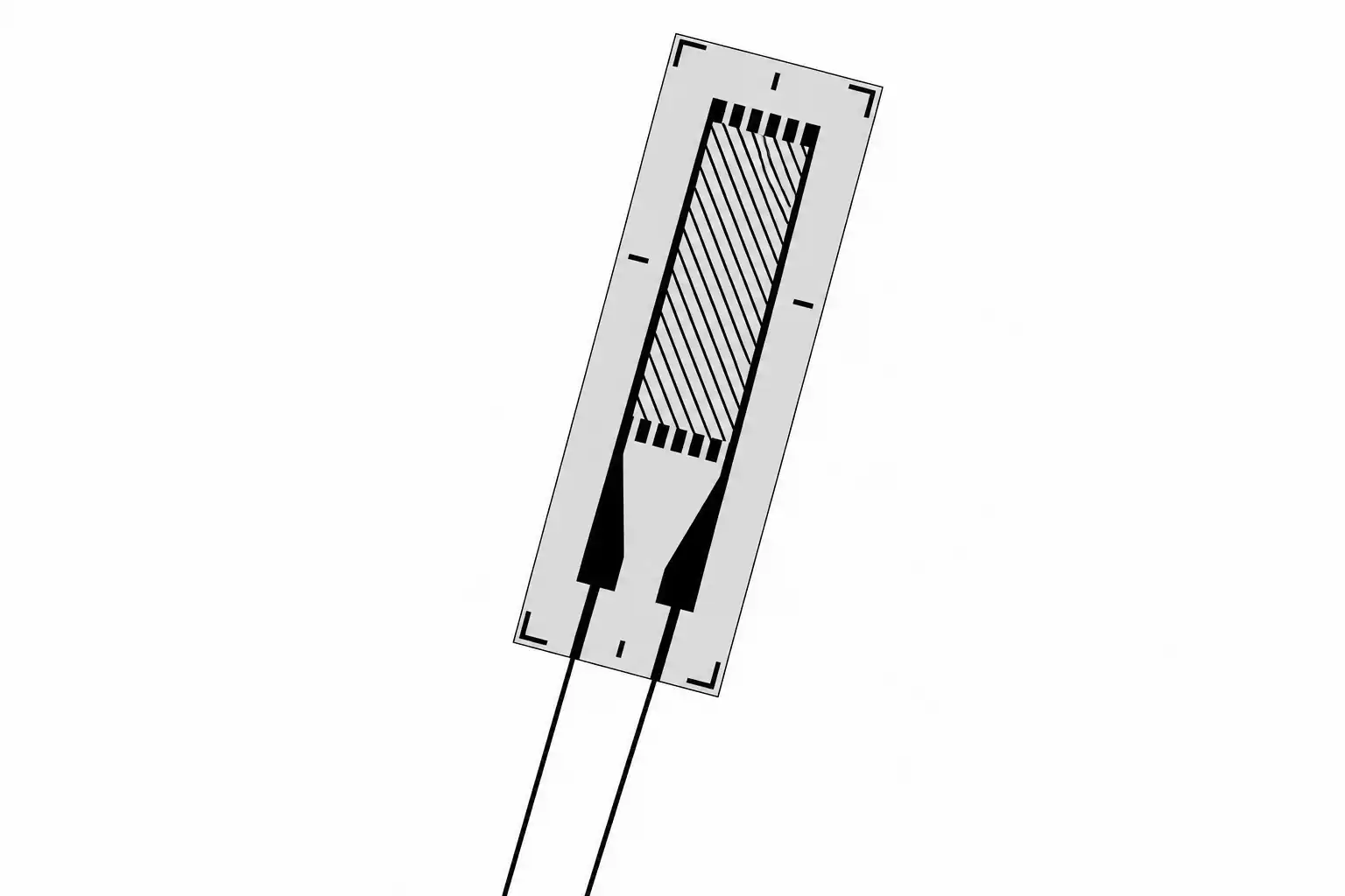
Figure 1. Metal-foil strain gauge
The metal-foil strain gauge consists of a metal alloy foil, typically constantan, in the form of a grid placed on a flexible polyimide backing. The backing material serves as an electrical insulator from the metal part to which the gauge is attached. The gauge is bonded using adhesive to the surface of the part whose strain needs to be measured.
Some gauges are made with the lead wires already attached to the gauge, but other gauges provide an area where one can solder the lead wires. Standard rectangular gauges are made with grid gauge lengths varying from 1.5 to 25 mm and grid gauge widths varying from 1.2 to 8 mm.
Strain is defined as
$$\varepsilon =\frac{\Delta l}{l} \ \ \ \ \ (2)$$
where $\Delta l$ is the change in length of a part of length l. Using a strain gauge, the measured strain is obtained using the relationship
$$\varepsilon =\frac{1}{F}\frac{\Delta R}{R} \ \ \ \ \ (3)$$
where F is called the gauge factor and its value is provided by the strain gauge manufacturer. We will show next how Equation (3) was obtained. For this, consider a bar with a cross-sectional area A and length L. The resistance of the bar is given by
$$R=\frac{\rho L}{A} \ \ \ \ \ (4)$$
where ρ is the resistivity of the material. The area can be expressed as A=CD2, where C is a constant and D is the section dimension. For a square section, C = 1; for a circular section, C = π/4; etc. Equation (4) can be written as
$$R=\frac{\rho L}{CD^{2}}=f(\rho ,L,D) \ \ \ \ \ (5)$$
Differentiating Equation (5), we get
$$dR=\frac{\partial f}{\partial \rho }d\rho+\frac{\partial f}{\partial L }dL+\frac{\partial f}{\partial D }dD=\frac{L}{CD^{2}}d\rho+\frac{\rho }{CD^{2}}dL-2\frac{\rho L}{CD^{3}}dD \ \ \ \ \ (6)$$
Dividing Equation (6) by Equation (5), we get
$$\frac{dR}{R}=\frac{d\rho }{\rho } +\frac{dL}{L}-2\frac{dD}{D} \ \ \ \ \ (7)$$
But
$$\varepsilon_a=\frac{dL}{L} \qquad \varepsilon_l=\frac{dD}{D} \qquad \text{and} \qquad \nu=-\frac{\varepsilon_l}{\varepsilon_a} \ \ \ \ \ (8)$$
where $ \varepsilon _{a}$ is the axial or longitudinal strain, $ \varepsilon _{l}$ is the lateral strain, and ν is the Poisson’s ratio. Replacing the terms in Equation (7) by the equivalent terms in Equation (8), we get
$$\frac{dR}{R}=\frac{d\rho }{\rho } +\varepsilon _{a}+2v\varepsilon _{a} \ \ \ \ \ (9)$$
Dividing Equation (9) by $ \varepsilon _{a}$, we get
$$\frac{dR/R}{\varepsilon _{a}}=\frac{d\rho/\rho }{dL/L }+1 +2v \ \ \ \ \ (10)$$
The right-hand side of Equation (10) is termed the gauge factor F. The value of F depends on the Poisson’s ratio ν of the strain gauge material, as well as on how its resistivity changes with strain. For Constantan, F is 2.0. From Equation (10), if we replace dR with $\Delta R$ we thus get
$$\varepsilon =\frac{1}{F}\frac{\Delta R}{R} \ \ \ \ \ (11)$$
In most cases, the strain is a small quantity, and the term microstrain is used where the strain is multiplied by one million.
Strain gauges are manufactured with standard resistances ranging from 120 to 1000 Ω, with both 120 Ω and 350 Ω being common, especially the 350 Ω in applications like load cells.
When these gauges are subjected to mechanical deformation, the change in their resistance is typically small, often amounting to less than a fraction of one percent of the gauge’s nominal resistance. Example 1 illustrates this point. To improve sensitivity and compensate for factors like temperature-induced resistance changes, strain gauges are typically incorporated into a Wheatstone bridge circuit. This configuration can measure resistance changes more precisely than a standard ohmmeter, especially when detecting the small resistance changes associated with strain.
Example 1 Strain Under Axial Loading
A 2-cm diameter steel ( $\begin{matrix}E=200\times 10^{9} & Nm^{2} \end{matrix}$ ) rod is subjected to a tensile axial force of 2500 N. Assume a strain gauge with a resistance of 120 Ω and a gauge factor F of 2 is used to measure the strain due to this loading. Determine the change in resistance of the gauge under this loading.
Solution
The stress due to this loading is given by
$$\sigma =\frac{F}{A}=\frac{2500}{\pi (0.01^{2})} =7.96 MPa$$
The strain is obtained from Equation (1), which gives
$$\varepsilon=\frac{\sigma}{E}=\frac{7.96\times10^{6}}{200\times10^{9}}=39.8\,\text{microstrain}$$
The change in resistance of the strain gauge is then given by
$$ \Delta R=\varepsilon \times F\times R=39.8\times 10^{-6}\times 2\times 120=0.00955\Omega $$
Note that the change in resistance is very small (0.008%) and cannot be precisely read from an ordinary ohmmeter, which does not have such a sensitivity.
Strain gauges are used in a variety of applications. In addition to their use in directly measuring the strain and the resulting stresses on members subjected to loading, they are also used in the construction of force and torque sensors, some types of pressure sensors, and temperature sensors, since they can measure the elongation due to a temperature change.
Due to its finite size, a strain gauge measures only the average strain over an area and not the exact strain. This approximation is acceptable in cases where the strain is uniform, but it can lead to errors in cases where the strain changes considerably, such as in stress concentration areas.
While the single, linear-pattern strain gauge (Figure 1) is common, strain gauges are also made with many other configurations. These include:
- The dual-grid gauge (Figure 2(a)) that is typically used to measure bending strain,
- The biaxial strain gauge (Figure 2(b)) to measure axial strain, where the principal strain directions are generally known, such as in pressure vessels, and
- The three-element rosette (Figure 2(c)) to measure strain in cases where the principal strain directions are not known in advance.
The biaxial and the three-element rosette gauges are available with the grids stacked as in Figure 2(b) or in planar form (Figure 2(c)). The stacked configuration is more compact, but it is stiffer and less conformable than its planar counterpart.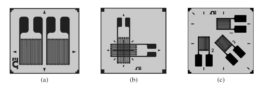
Figure 2. Other configurations of strain gauges: (a) dual-grid gauge, (b) biaxial, and (c) three-element rosette
Key Takeaways
Strain gauges are fundamental sensing elements in structural analysis, mechanical testing, and industrial instrumentation because they enable precise measurement of deformation under load. Their integration into bridge circuits allows detection of extremely small resistance changes, making them essential components in load cells, torque sensors, pressure transducers, and structural health monitoring systems. Understanding gauge factor, material behavior, temperature sensitivity, and proper gauge configuration ensures accurate stress evaluation and reliable performance across applications ranging from laboratory experimentation to aerospace, automotive, and civil engineering systems.