In this article, you’ll learn about microcontroller components and their functions including Ports and Registers, Stack Pointer and Program Pointer, ALU, Oscillator, Watchdog Timer, Memory, and Programmable Memory.
Microcontroller Block Diagram
The microcontroller consists of thousands of digital circuits. These digital circuits are combined into areas that provide specific functions. Examine Figure 1. The simplified microcontroller block diagram illustrates how the major sections inside the microcontroller work together to process the program instructions.
The components of the microcontroller are used to save data and programs, perform math and logic functions, and generate timing signals. The different areas are connected by a bus system.
The bus system contains tiny parallel circuits that carry the digital pulse patterns from section to section.
The ROM stores the program required for the microcontroller to function. The ROM controls how the chip components operate and how data and instructions flow through the chip.
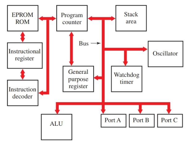
Figure 1. A simplified block diagram of a typical microcontroller. All the major components are connected together by a bus system. Data and instructions are moved around the chip via the bus.
What are the Components of a Microcontroller?
The core microcontroller components include:
- Ports and Registers
- Stack Pointer and Program Pointer
- ALU
- Oscillator
- Watchdog Timer
- Memory
- Programmable Memory
Ports and Registers
There are many different types of registers and ports found inside a microcontroller chip.
Ports and registers are special memory locations dedicated to a specific function such as a hardware location or a place to manipulate data.
Some ports correspond to the input and output pin assignments of the chip. By placing a one or zero into a specific port address, you can change the pin assignment of the microcontroller from an input pin to an output pin.
Ports can also contain information sent to the pins on the microcontroller chip from sensors or switches. The contents can then be stored in memory or remain in the port.
A register can be used to hold the contents of data being manipulated. For example, when performing a mathematical operation, the data being manipulated must be stored in two different registers and the result placed in a third register. See Figure 2.
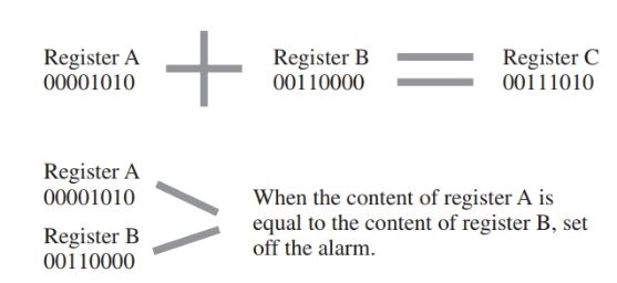
Figure 2. The contents of the two registers can be compared to determine if an action should begin.
In the illustration, you see three registers labeled as A, B, and C. The content of register A and the content of register B are added together and then stored in register C.
Another typical use of a register is to store a value to be compared to another register value. For example, compare the content of register A to the content of register B. If the values are identical, an action is initiated such as turning on a valve, activating a door switch, or turning on an alarm.
The contents of the two registers, A and B, could compare a temperature rise to a preset value, or the distance moved by a robotic arm. As you work with programs and memory, the use and applications for registers will become more apparent.
Stack Pointer and Program Counter
The area in memory that is used to store data and program information is called the stack.
The most common use of the stack is to store the program address of the next instruction to be executed. Since the processor processes command sequentially, one after the other until complete, it relies on the stack to temporarily store the address of the next instruction in case the main program is interrupted.
A special device called the stack pointer keeps track of the last stack location used while the processor is busy manipulating data values, checking ports, or checking interrupts. Look at Figure 3.
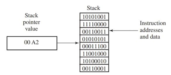
Figure 3. The stack pointer is responsible for keeping track of the sequence of memory locations, referred to as the stack, while the computer is manipulating data and checking interrupts.
Interrupts are, as the name implies, a way to interrupt the processor while it is processing instructions and data to perform a different task. The interrupts come in two varieties: hardware interrupts and software interrupts.
- You May Also Read: What is a Microcontroller | Basics | Advantages & Disadvantages
An example of a hardware interrupt is when input pin number 3 receives an electrical signal from a push button, and the microprocessor stops what it is doing to respond to the signal. While it is responding to the push button signal (a hardware interrupt), the contents of the program counter are pushed onto the stack.
The stack pointer bookmarks the location of the last item pushed onto the stack. When the processor finishes servicing the interrupt, the counter address is popped from the stack and returned to the program counter, and the microprocessor continues processing the instructions in order.
ALU
The arithmetic/logic unit (ALU) performs common mathematical and logical operations on data. Some typical logic functions are similar to the AND, OR, NOT, NOR, and NAND digital gates.
Oscillator
The oscillator is a complex digital device that requires a steady digital pulse for timing. All of the separate functions are controlled by one central timing system.
The timing pulse provides the basis for a proper sequence of all the separate sections of the microcontroller chip. The source of the steady pulse rate is the oscillator circuit.
Watchdog Timer
A specialized program often found as part of the microcontroller is called a watchdog timer. The watchdog timer is designed to prevent the microcontroller from halting or “locking up” because of a user-written program.
Remember that a processor processes instructions step-by-step. It will wait until one instruction is completed before processing the next.
A problem can arise if a command is issued to a processor that cannot be accomplished. For example, a program is written by a user and contains an instruction calling for checking the input value of I/O pin 36. If there is no I/O pin 36, the microcontroller will wait forever for input. It will not process the next command until it receives input on pin 36. Without the watchdog timer, the microcontroller would halt and thus fail to process further instructions.
The watchdog timer uses a routine that is based on timing. If a program has not been completed or repeated as a loop within a certain amount of time, the watchdog timer issues a reset command.
A system reset sets all the register values to zero. The reset feature allows the controller to recover from the crash. It releases the program and sets the controller to start over again.
Memory
Microcontrollers and computers use various types of memory. These types of memory are usually referred to by acronyms.
The two broad classifications of memory are random access memory (RAM) and read-only memory (ROM). These two types of memory are classified according to their function as memory units.
Random access memory (RAM) is used in the microcontroller just as it is in the computer, to temporarily store programs and data. It is a volatile memory, which means it loses its contents when electrical power is no longer applied to the memory chip. Power can be lost due to power failures or by simply turning off the power switch.
Read-only memory (ROM) is used to permanently store a program or data and retain the information even when the power is disconnected from the unit. It is described as a nonvolatile memory.
Programmable Memory
ROM is classified as to how it is constructed and how the program code inside the chip can be altered.
Masked ROM (usually referred to as just ROM) is a special type of memory that is permanently programmed during the manufacturing process. Masked ROM memory cannot be reprogrammed. To change the program in a system using masked ROM, you must use an entirely different masked ROM chip.
Programmable read-only memory (PROM) is a memory that is programmed after it is manufactured. It is manufactured with thousands of empty memory cells.
A program writer “burns” a pattern into the empty cells, forming a program in the blank PROM chip. Like masked ROM, a PROM chip program is permanent for the life of the chip.
Erasable programmable read-only memory (EPROM) is a special type of PROM that can be reprogrammed many times. When manufactured, a small window is left on the chip. Any program entered into the chip can be erased at a later time by shining an ultraviolet light through the window on the chip. The chip can then be reprogrammed using a programming device.
Electrically erasable programmable read-only memory (EEPROM) is a type of memory chip that can be erased electrically and then reprogrammed. It is commonly used for the computer BIOS chip.
A microcontroller is usually constructed with a PROM on the chip itself containing the basic set of instructions for running the microcontroller and its internal parts. This program is permanent and not alterable.
In addition to the basic ROM, another section of memory is used to store programs written by the user. It typically contains a small EEPROM memory area. If larger program storage is required, additional EEPROM chips can be connected to the microcontroller.
Microcontroller Components Key Takeaways
Understanding the key components of a microcontroller—such as ports and registers, the stack pointer and program counter, the ALU, oscillator, watchdog timer, and various types of memory—is essential for designing and implementing efficient embedded systems. These components work together to perform critical tasks like data processing, memory management, timing control, and input/output handling. Their integration allows microcontrollers to operate autonomously and reliably in countless real-world applications, from industrial automation and robotics to consumer electronics and automotive systems.