In two winding transformer, whole power is transferred from primary to secondary side by means of induction ONLY While, in the case of Auto transformer, part of the whole power is transferred by induction and rest of the power is transferred through conduction.
In two-winding transformers, primary and secondary windings are wounded on separate limbs or interleaved means one winding over the other one concentrically and insulation is retained in between). So, fundamentally both the windings are isolated from each other electrically and connected ONLY magnetically by means of flux. So whatever power is transferred to secondary side is through induction ONLY (induced emf in secondary winding).
In the case of Autotransformer, there exists ONLY one winding, part of which is common between primary and secondary. That means by this mutual winding both primary and secondary windings are linked electrically and hence the power transferred because of this common winding, is essentially by conduction. The power transferred, because of winding which is not mutual (common) between primary and secondary, is by induction.
In this article, the main differences between Autotransformer and Conventional transformer are discussed on the basis of construction, insulation, induction mechanism, size, cost, power transfer, connections, efficiency, losses, excitation current, output voltage, and applications.The following table explains the key Differences between Autotransformer and Conventional Transformer in terms of construction, operation, working principle, and applications.
Difference between Autotransformer and Conventional Transformer
Characteristics Conventional Transformer Autotransformer
Construction A transformer consisting of three pairs of winding used to transform a set of three-phase voltages from one voltage level to another. A transformer with a single electric winding, which can be used as a step-down or step-up device.
Insulation Primary and secondary windings are insulated electrically. Primary and secondary windings are not insulated electrically.
Representation 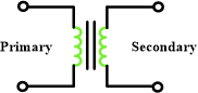
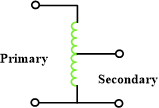
Induction Principle Uses mutual induction Self-induction as there is only ONE winding
Windings There can be multiple windings like primary, secondary, and tertiary There is ONLY one winding which serves as a primary as well as secondary.
Size Large in size because of separate (multiple) windings Small as there is only ONE winding
Material for winding These type of transformers utilize more material in terms of winding They require less material for winding
Economical Less economical because of bigger size and maintenance Much more economical as compared to their counter-part
Cost for same VA rating More costly Less costly
Power transfer Through induction ONLY Through induction as well as direct electrical connection
Circuit connection Primary and secondary and coupled (connected) magnetically. Primary and secondary and coupled (connected) magnetically as well as electrically.
Impedance Possesses high impedance Less impedance as compared to conventional transformer
Efficiency Less efficient in terms of operation and maintenance Much more efficient
Losses More windings so more losses Losses are significantly less
Output voltage Constant (unless taps are employed) Variable (can be changed if needed easily)
Excitation current Large current is needed Small current is required
Applications Use to step-up and step-down the voltage in transmission and distribution systems Widely used as Voltage regulator , Starter in an induction machine, Boosters in an AC feeders to increase the voltages
You May Also Read:
Difference Between Current Transformer and Potential Transformer
Difference Between Core Type and Shell Type Transformers