The article discusses the generation of electromotive force (EMF) through the interaction between a conductor and a magnetic field, covering key principles such as Faraday’s Law, factors affecting EMF generation (magnetic field density, conductor length, motion velocity, and angle), and the mathematical formulas for calculating induced voltage. It highlights the importance of these principles in electrical machines and systems where voltage is generated through rotating conductors.
Induced EMF Definition
An EMF can be induced in a conductor if the conductor cuts across or is cut across by a magnetic field. That is to say,
when there is a relative movement between a conductor and a magnetic field, a current will be induced in the conductor if there is a complete circuit.
Michael Faraday found that the voltage generated in a coil due to a changing magnetic field is directly proportional to the change in flux, and inversely proportional to the change in time. He also noted that increasing the number of conductors, or turns of a coil, is equivalent to increasing the current.
Faraday’s Law
The value of the EMF induced in a circuit depends on the number of conductors in the circuit and the rate of change of the magnetic flux linking the conductors.
Induced EMF Formula
In mathematical terms, formula for an induced EMF can be written as:
\[V=N\frac{\Delta \phi }{\Delta t}\]
Where:
- V = induced voltage
- N = number of turns
- ΔΦ = flux change in webers
- Δt =time change in seconds
In engineering and science, the generated voltage is often denoted by the letter E for EMF, so the following formula represents the same law:
\[E=N\frac{\Delta \phi }{\Delta t}\]
Example 1
A coil of 500 turns has a permanent magnet moved into it such that 0.2 Wb cuts across the coil in 4 seconds.
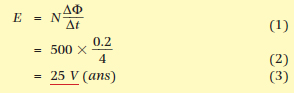
$$ E=N\frac{\Delta \Phi }{\Delta t}=500\times \frac{0.2}{4}=25V$$
Example 2
A coil of 600 turns has a flux of 80 μWb passing through it. If the flux is reduced to 30 μWb in 15 ms, find the average induced voltage.
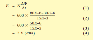
$$ E=N\frac{\Delta \Phi }{\Delta t}=600\times \frac{80E-6-30E-6}{15E-3}=600\times\frac{50E-6}{15E-3}=2V$$
Factors Affecting Generated EMF
The parameters that determine the magnitude of the generated EMF are therefore:
- the magnetic field density (B)
- the length of the conductor within the field (l)
- the relative motion between conductor and field (v)
- the angle between the field lines and the path of the conductor (sinθ).
An EMF is generated by the continuous rotation of a conductor through a magnetic field; this is the most important method of generation of electricity, so important that it is the basis of all rotating electrical machines.
Magnetic Field Density
The magnetic field density (B) is determined by the total flux produced by the magnet (Φ) and the area of the magnetic field (A). As the total flux spreads out over any area available, flux density often refers to the flux in a given area, such as the area directly between two magnetic poles.
The magnetic field density or flux density can be changed by changing the magnets or the magnetic path that the field passes through. An electrically produced magnetic field can be changed by changing the current flowing in the coil or the number of turns of that coil.
Length of the Conductor
The conductor length can be increased by increasing the area of the magnetic field that the conductor passes through, while keeping the magnetic field strength constant.
However, the most common method of increasing the length of the conductor within a given space is to add more conductors. As the conductor is usually wound in a coil, the length must be multiplied by the number of turns in the coil passing through the flux (N).
Therefore, the total length of a conductor is the actual length multiplied by the number of conductors.
Velocity of Motion of the Conductor
A conductor passing through a magnetic field over a given time generates a voltage proportional to the field through which it passes.
If the conductor travels faster, then it will pass through more of the magnetic field in the same time and the voltage generated will be greater. The most obvious way to change the voltage, therefore, is to change the speed at which the conductor travels. This is achieved by changing the rotational speed of the machine.
Traditionally, rotational speed is given in revolutions per minute (rpm) and speed is given in revolutions per second (rs−1) or radians per second (rad s−1). One revolution per second equals 2π radians per second.
Angle of the Conductor Path
A second factor that changes the effective speed or velocity of the conductor is the angle between the magnetic field and the path of the conductor.
At 90° to the field flux the voltage generated will be the greatest, and at 0° the voltage will be zero! This is because at 0° the conductor is travelling parallel to the magnetic field and will not cut across any magnetic lines of force. The value of the voltage will therefore be between 0 volts and 1 volt of the maximum voltage generated. Those familiar with trigonometry should see that the value is proportional to the sine of the angle.
Generated EMF
Combining these factors results in a formula for the EMF generated in a coil.
\[E=Blv\sin \theta \]
While the average electrician may not use this formula to calculate the EMF generated in a coil, the formula is important in establishing and remembering that the voltage is proportional to the number of turns, the field density, the relative velocity between the conductor and the field, and the angle that the motion makes with the axis of the field. Figure 2 shows the path a conductor takes in one revolution.
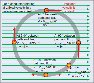
Figure 2 Conductor Path Through a Magnetic Field
Example 3 shows that, for a given conductor length and velocity in a given field, all of which remain constant, the voltage generated is directly proportional to the sine of the angle between the conductor path and the axis of the magnetic field. When the path is parallel with the magnetic field, at θ = 0º, no voltage is generated, as the conductor does not cut across the magnetic fields. When the path is at right angles to the magnetic field, at θ = 90º, the full voltage is generated; in Example 3 this is 1 volt.
Example 3
A 10 cm conductor is rotated within a magnetic field of a constant density of 1 Tesla. If the velocity relative to the field is 10 m per second, what voltage will be generated at each of the angles … 0º, 30º, 45º, 60º and 90º?
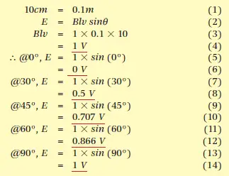
$$10cm=0.1m$$
$$E=\textrm{Blv sin}\theta $$
$$Blv=1\times 0.1\times 10=1V$$
$$\therefore @0^{\circ},E=1\times sin\left ( 0^{\circ} \right )=0V$$
$$ @30^{\circ},E=1\times sin\left ( 30^{\circ} \right )=0.5V$$
$$ @45^{\circ},E=1\times sin\left ( 45^{\circ} \right )=0.707V$$
$$ @60^{\circ},E=1\times sin\left ( 60^{\circ} \right )=0.866V$$
$$ @90^{\circ},E=1\times sin\left ( 90^{\circ} \right )=1V$$
At any angle between 0º and 90º the voltage will be between 0 volts and 1 volt. The actual value is calculated using E = Emax × sin(θ). Note that the value increases from 0º to 90º, then reduces again to 0 volts at 180º. The voltage then becomes negative from 180º to 270º when it is −1 V and returns to 0 V at 360º.
Generation of an EMF in a Magnetic Field Key Takeaways
The principles of induced EMF and Faraday’s Law are fundamental in many practical applications, especially in the generation of electricity through rotating conductors, which forms the basis of electrical machines such as generators and motors. Understanding the factors that influence EMF, such as magnetic field density, conductor length, motion velocity, and the angle between the conductor and magnetic fields, is crucial for optimizing energy generation and improving the efficiency of electrical systems used in industries, transportation, and renewable energy sources.