The article covers the concepts of wire gauge sizes, circular mils, and specific resistance, explaining how wire dimensions and material properties affect electrical resistance. It also discusses types of transmission lines like twin-lead and coaxial cables, along with a comparison of copper and aluminum conductors.
In order to compare the resistance and conductor sizes with each other, we need to establish a convenient unit. This unit is the mil-foot (mil-ft). A conductor will possess this unit size if having one mil (0.001 inches) diameter and a length of one foot.
The standardized unit for wire cross-sectional area is circular mil. Since the round conductor’s diameter is generally a small fraction of an inch, it is quite handy to demonstrate them in mils, which is equivalent to 1/1000 of an inch, for avoiding the use of decimals.
For instance, the conductor diameter can be stated as 25 mils instead of 0.025 in. A circular mil, in fact, is the area of a circle whose diameter is one mil, as depicted in figure 1.
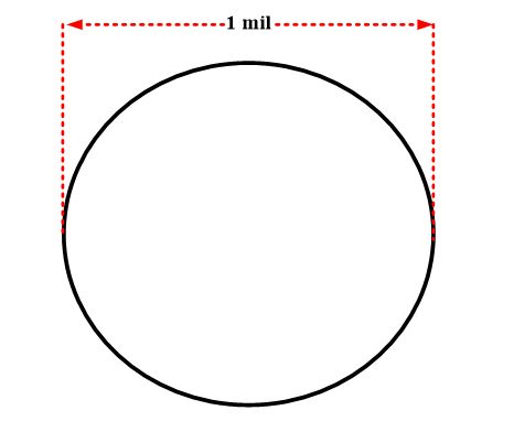
Figure 1: Circular Mil
The area of a round conductor in circular mils is acquired by squaring up the diameter which is calculated in mils. This convention is an engineering agreement which is in practice for last many decades and is not quite associated with the circle area being equivalent to $\pi {{r}^{2}}$.
Example
What is the circular mil area of a round conductor with a diameter of 25 mils?
Solution
$A={{d}^{2}}={{25}^{2}}=635\text{ c}\text{.mils}$
A circular mil-foot, as demonstrated in figure 2, is, in reality, a volume unit. It holds a one circular mil cross-sectional area and a length of one foot. Since it is conceived a unit conductor, the circular mil-foot is very valuable in order to make comparisons between conductors formed of dissimilar metallic elements. For instance, a resistivity comparison of different conductors’ types can be made by finding out the resistance of a circular mil-foot of each conductor.
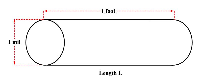
Figure 2: Circular Mil-Foot
Specific Resistance or Resistivity
The resistance of a conductor expressed in ohms per unit length per unit area, that is, per circular mil-foot.
Specific Resistance can be described as the resistance (calculated in ohms) offered by a unit volume (which is equivalent to the circular mil-foot) of a substance (material) to the electrical current flow. A substance that possesses higher resistivity will offer low conductivity, and vice versa. For instance, the cooper specific resistance is $10.4\text{ }{}^{\Omega }/{}_{mil-ft}$ . Put differently, a copper conductor of the cross-sectional area and a length of 1 foot possesses 10.4 Ω resistance.
A list of specific resistivities of several different types of materials is given in table 1. The values indicated are based on 20 oC.
Material Resistivity
Silver 9.56
Copper 10.4
Gold 14
Aluminum 17
Tungsten 34
Brass 42
Iron 61
Nichrome 675
Table 1: Specific Resistivities (${}^{\Omega }/{}_{c.mil-ft}$ at 20 oC)
Calculation of Resistance
The relationship of specific resistance, length, and cross-sectional area is given by the following equation:
$R=\rho \frac{L}{A}$
Where
ρ= specific resistance
L= length in feet
A= cross-section area in circular mils
The following example illustrates the use of this formula.
Example
Calculate the resistance of a piece of copper wire at 20 oC if it is 25 ft long and 40 mils in diameter.
Solution
$A={{d}^{2}}={{40}^{2}}=1600\text{ c}\text{.mils}$
Substitute in the above-mentioned formula, we come up with
$R=10.4*\frac{25}{1600}=0.163\text{ }\Omega $
American Wire Gauge
The system of notation for measuring the size of conductors or wires.
Wires are manufactured in sizes numbered according to the American wire gage (AWG). Some of these numbers appear in Table 1. Notice that the wire diameters become smaller as the gage numbers increase. In typical applications, where the current is mill amperes, a #22 number wire would be used. By comparison, a #14 wire is customarily used in residential-lightning circuits and #12 for wall plugs. When any conductor is selected, consideration must be given to the maximum current it can safely carry and the voltage its insulation can stand without breakdown.
Gage number Diameter (mils) Circular mil area Ohms per 1000 ft
0 365 133000 0.0795
0 325 106000 0.1
1 289 83700 0.126
2 258 66400 0.159
3 229 52600 0.201
4 204 41700 0.253
5 182 33100 0.319
6 162 26300 0.403
7 144 20800 0.508
8 128 16500 0.641
9 114 13100 0.808
10 102 10400 1.02
11 91 8230 1.28
12 81 6530 1.62
13 72 5180 2.04
14 64 4110 2.58
15 57 3260 3.25
16 51 2580 4.09
17 45 2050 5.16
18 40 1620 6.51
19 36 1290 8.21
20 32 1020 10.4
21 28.5 810 13.1
22 25.3 642 16.5
23 22.6 509 20.8
24 20.1 404 26.2
25 17.9 320 33
26 15.9 254 41.6
27 14.2 202 52.5
28 12.6 160 66.2
29 11.3 127 83.4
30 10 101 105
31 8.9 79.7 133
32 8 63.2 167
33 7.1 50.1 211
34 6.3 39.8 266
35 5.6 31.5 335
36 5 25 423
Table.2: American Wire Gauge (AWG) Wire Sizes
Copper is most frequently used for wire conductors because it has a low resistance per unit length, is less expensive than silver or gold, and is easily solderable. The copper is usually tinned (covered with a thin coating of solder) and may be solid or stranded.
Twin-lead transmission line
A type of transmission line comprised of two parallel conductors covered by a solid insulation.
Coaxial cable
A transmission line in which one conductor is concentric to another and separated by a continuous solid dielectric spacer.
Many electric cables are used in industry to interconnect components. Cables consist of two or more conductors within a common covering. Figure 1 shows a typical 300 Ω twin-lead transmission line, or cable, such as used in TV to connect the antenna to the receiver.
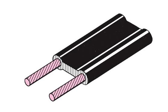
Figure 3: Twin-Lead Transmission Line
The cable shown in figure 2 is a coaxial cable, which is used extensively for conducting high-frequency currents and consists of an inner conductor surrounded by polyethylene or other highly resistive insulation. Over the insulation is a flexible, tinned copper braid, which is in turn enclosed in a vinyl jacket. The inner conductor and braid constitute the two leads.
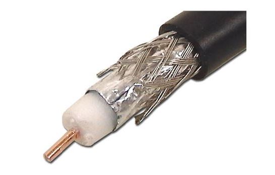
Figure 4: Coaxial Cable
Aluminum Conductors
Although aluminum has only about 60 % of the conductivity of copper, it is much lighter in weight than copper and is now frequently used by the electrical power companies. Because aluminum conductors are not easily soldered, lugs, or terminals, are generally fastened to them by special tools.
Wire Gauge Sizes and Circular mils Key Takeaways
Understanding wire gauge sizes, circular mils, and specific resistance is crucial in electrical engineering and practical applications because these parameters directly affect how efficiently electricity is transmitted through conductors. Accurately calculating resistance based on material type and dimensions allows engineers to design safe and effective electrical systems, ensuring minimal energy loss and optimal performance. The comparison between copper and aluminum conductors, along with knowledge of transmission line types such as twin-lead and coaxial cables, is essential when selecting the right materials for residential, commercial, and industrial installations.