The article provides an overview of how resistors in series and parallel circuits function, focusing on methods to calculate total resistance, voltage drops, and current flow in various configurations. It also covers the use of series and parallel resistor combinations in voltage and current divider circuits, including examples and formulas.
Learning Outcomes
- Calculate the total resistance of different resistor combinations i.e., series, parallel, and series-parallel.
- Show how resistors are used as voltage and current dividers.
- Calculate the resistance and wattage value for a series voltage dropping resistor.
Individual resistors can be connected together in a series connection, a parallel connection, or combinations of both series and parallel together. This results in a more complex circuit whose total circuit resistance is a combination of the individual resistors.
Resistors is Series
To connect resistors in series, they are joined end to end together in a single line as illustrated in Figure 1. The characteristics of series connected resistors can be summarized as follows:
- The total resistance of the circuit (RT) increases if additional resistors are connected in series and decreases if resistors are removed.
- To determine the total resistance of the circuit, simply find the sum of the individual resistance loads.
- In this example, if the resistors are labeled R1, R2, and R3, then the total resistance RT is calculated using the formula
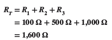
Figure 1 Resistors connected in series.
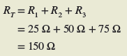
Calculating Equivalent Resistance in Series Circuit Example 1
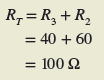
Three resistors, R1 (4 Ω), R2 (50 Ω), and R3 (75 Ω) are connected in series as shown in Figure 2. Determine the value of the total combined circuit resistance.
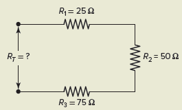
Figure 2 Circuit for Example 1.
Solution:
Resistors connected in series are used as voltage dividers, as illustrated in the circuit of Figure 3. Voltage dividers are widely used in circuits where a single voltage source must supply several different voltage values for different parts of a circuit.
The characteristics of a series voltage divider circuit can be summarized as follows:
- The same amount of current flows through each resistor.
- The input voltage is divided proportionally across the series-connected resistors.
- The voltage drop across a resistor in a series circuit is directly proportional to the ohmic value of the resistor.
- The higher the resistance value, the greater the voltage drop.
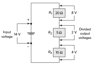
Figure 3 Voltage divider circuit diagram
For a voltage divider circuit, the voltage dropped across each resistor is normally a factor that needs to be determined. The voltage drop across any one resistor is proportional to the ratio of its resistance value to that of the total circuit resistance.
The voltage divider formula allows you to calculate the voltage drop across any one of the resistors connected in series without having to first calculate the value of circuit current. Stated as a formula:
![]()
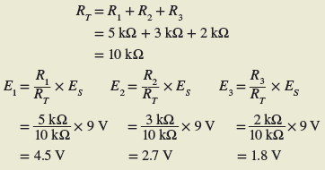
Calculating Voltage Drop in Series Circuit Example 2
Resistors R1 (5 kΩ), R2 (3 kΩ), and R3 (2 kΩ) are connected in series to form a voltage divider as shown in Figure 4. If an input voltage of 9 volts is applied to the circuit, calculate the value of the voltage drop across each of the resistors, using the voltage divider formula.
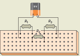
Figure 4 Circuit for Example 2.
Solution:
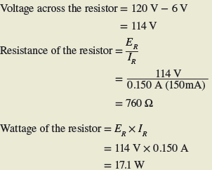
Calculating Series Dropping Resistance Value and Wattage Example 3
You have a 120-V source and want to use a series dropping resistor in conjunction with a 6 V @ 150 mA pilot light to indicate when power is applied (Figure 5). Determine the series dropping resistance value and wattage required.
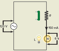
Figure 5 Circuit for Example 3.
Solution:
Resistors is Parallel
Resistors are connected in parallel by connecting them side by side across one another, as illustrated in Figure 6. Note that the two ends of the resistors are connected to the same two points.
The characteristics of parallel-connected resistors can be summarized as follows:
- The total resistance (RT) of the circuit formed is less than that of the lowest value of resistance present in any of the branches.
- Each resistor provides a separate parallel path for the current to flow.
- If you have several resistors of the same value in parallel, then the total resistance is found most easily by dividing the common resistance value by the number of resistors connected. For three 150-Ω resistors in parallel the total resistance is
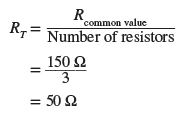
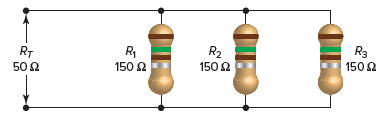
Figure 6 Resistors connected in parallel.
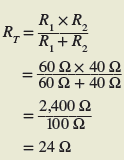
To find the total resistance of two unequal values of resistors connected in parallel (a very common use) the product over sum formula is used. This formula is
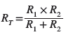
Calculating Equivalent Resistance in Parallel Circuit Example 4
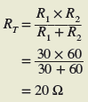
A 60-Ω resistor is connected in parallel with one of 40 Ω, as shown in Figure 7. Determine the value of the total combined resistance of the two using the product over sum formula.
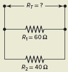
Figure 7 Circuit for Example 4.
Solution:
The product over sum formula works best for two resistors in parallel. Where more than two resistors are in parallel, it becomes more difficult, and less practical, to use. For more than two unequal resistor values connected in parallel, the general formula for total resistance of a parallel circuit is used. This formula is
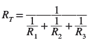
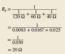
Calculating Equivalent Resistance in Parallel Circuit Example 5
Three resistors, R1 (120 Ω), R2 (60 Ω), and R3 (40 Ω) are connected in parallel, as shown in Figure 8. Determine the value of the total combined circuit resistance.
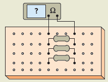
Figure 8 Circuit for Example 5.
Solution:
Parallel resistor circuits can be considered as current dividers because the current splits or divides between the various resistors, as illustrated in Figure 9.
The characteristics of a parallel current divider circuit can be summarized as follows:
- Current flow through each branch resistor is inversely proportional to its resistance value.
- The smaller the resistance value, the greater the current flow and vice versa.
- Resistors of the same ohmic value will have the same amount of current through them.
- The formula describing a current divider is similar in form to that for the voltage divider and can be expressed as follows:
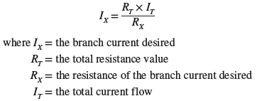
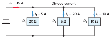
Figure 9 Current divider circuit.
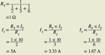
Calculating Current Flow in Parallel Circuit Example 6
Resistors R1 R2 and R3 (2 Ω, 3 Ω, and 6 Ω, respectively) are connected in parallel, as shown in Figure 10. Use the current divider formula to calculate the value of the current flow through each of the load resistors if the total current flow to the circuit is 10 amperes.
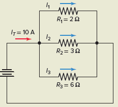
Figure 10 Circuit for Example 6.
Solution:
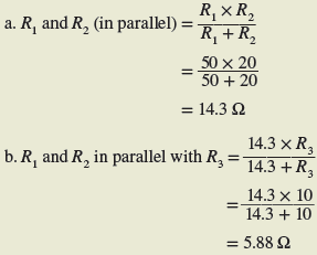
Calculating Equivalent (Total) Resistance in Parallel Circuit Example 7
As additional loads are connected in parallel the total resistance of the circuit decreases. For the circuit shown in Figure 11, determine the total circuit resistance under each of the following operating conditions:
- Switches 1 and 2 closed.
- Switches 1, 2, and 3 closed.
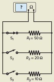
Figure 11 Circuit for Example 7.
Solution:
Resistors in Series-Parallel Combination
Combination resistive circuits, otherwise known as series-parallel resistive circuits, combine resistors in series with resistors in parallel, as shown in the Figure 12.
The rules governing these circuits are the same as those developed for series circuits and for parallel circuits. First, the resistance of the combined total resistance of the parallel portion is found. Then the total resistance of the parallel section is added to any series resistance to find the total resistance of the series-parallel combination circuit.
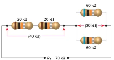
Figure 12 Series-parallel connection of resistors.
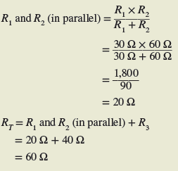
Calculating Equivalent Resistance in Series-Parallel Circuit Example 8
A 9-Ω resistor, R1, and a 60-Ω resistor, R2, are connected in parallel with each other and in series with a 40-Ω resistor, R3, as shown in Figure 13. Determine the total resistance of this series-parallel combination of resistors.
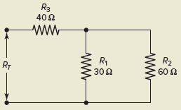
Figure 13 Circuit for Example 8.
Solution:
Calculating Equivalent Resistance in Series-Parallel Circuit Example 9
Resistance readings can be used to check circuits for fault conditions. As determined in the previous example, the normal total resistance of this series-parallel circuit arrangement of Figure 14 is 60 ohms.
- Find what the new value of RT would be should resistor R1 be faulted open while the resistance values of R2 and R3remain the same.
- Similarly, find what the new value of RT would be should resistor R3 be faulted shorted while the resistance values of R1and R2 remain the same.
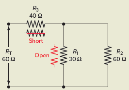
Figure 14 Circuit for Example 9.
Solution:
- With R1 faulted open, the circuit would consist of R3 in series with R2 and the total resistance would be:
- With R3 faulted shorted, the circuit would consist of R1 in parallel with R2 and the total resistance would be:
Resistors in Series and Parallel Review Questions
- Calculate the total resistance for each of the following resistor circuits:
- Series circuit: R1=40 Ω, R2=75 Ω
- Parallel circuit: R1=200 Ω, R2=200 Ω, R3=200 Ω
- Series circuit: R1=2,000 Ω, R2=6,000 Ω, R3=2,200 Ω
- Parallel circuit: R1=14 Ω, R2=32 Ω
- Series circuit: R1=4,700 Ω, R2=800 Ω, R3=200 Ω
- Parallel circuit: R1=60 Ω, R2=30 Ω, R3=15 Ω
- Resistors R1, R2, and R3 (50 Ω, 30 Ω, and 20 Ω, respectively) are connected in series across an applied voltage of 200 V to form a voltage divider. Using the voltage divider formula, calculate voltages E1, E2, and E3.
- The total current to two parallel-connected resistors is 3 A. The resistance of R1 is 10 Ω and the resistance of R2 is 40 Ω. Using the current divider formula, calculate currents I1 and I2.
- A 5-Ω resistor, R1, and a 20-Ω resistor, R2, are connected in parallel with each other and in series with a 6-Ω resistor, R3. Calculate the total resistance of this series-parallel circuit.
- You have been given three 100-Ω resistors to connect together. Describe the three circuit configurations possible, and calculate their total resistance values.
Answers
- (a) 115 Ω, (b) 66.7 Ω, (c) 10,200 Ω, (d) 9.74 Ω, (e) 5700 Ω, (f) 8.57 Ω
- E1 = 100 V, E2 = 60 V, E3 = 40 V
- I1 = 2.4 A, I2 = 0.6 A
- 10 Ω
- Three 100 Ω resistors connected in series, total resistance 300 Ω. Three 100 Ω resistors connected in parallel, total resistance 33.3 Ω. Two 100 Ω resistors connected in parallel and then connected in series with a 100 Ω resistor, total resistance 150 Ω.
Resistors in Series and Parallel Key Takeaways
Understanding how resistors function in series and parallel configurations is essential for designing and analyzing electrical circuits. These arrangements serve crucial roles in practical applications—series circuits are commonly used in voltage divider networks, which are vital for providing different voltage levels from a single power source, while parallel circuits are ideal for current division, allowing multiple components to operate independently from the same voltage supply. Furthermore, series-parallel combinations offer flexibility in controlling resistance and current paths in more complex electronic systems.
9 thoughts on “Resistors in Series and Parallel | Examples | Formula”