Inductance and capacitance are quite useful in electronic circuitry. One example of this usefulness is the filter. A filter is a circuit that separates specific frequencies.
There are many filter designs. For example, filters can be designed to pass low frequencies and reject high frequencies; to reject low frequencies and pass high frequencies, or to either pass or reject specified frequency bands.
Each filter type is named according to its function. There are four basic types of filters:
- low-pass,
- high-pass,
- band-pass, and
- band-reject.
Filters are also used to adjust a pulsating current coming from a rectifier. A rectifier is a device that converts ac into a pulsating dc. Because most electronic circuitry needs a pure direct current, the dc must be adjusted. This filter circuit levels out the peaks and valleys of the current.
Filtering Action
In the study of filtering action, these points should be reviewed:
- A capacitor will block a direct current but will pass an alternating current.
- A conductor can carry a current that has both a dc component and an ac component. The graph in part A of Figure 1 shows the flow of a steady 10-volt direct current. Part B of the figure shows an ac voltage whose peak value is 10 volts. Part C of the figure shows these two voltages combined. This wave depicts the sum of the two waves.
Note the new axis of the ac voltage. It now varies above and below the 10-volt dc level. Because the axis has been raised by the dc voltage, the ac voltage no longer reverses polarity. This current is a varying direct current.
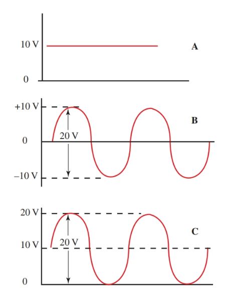
Figure 1. A–Steady direct current. B–10-volt peak alternating current. C–Combined dc and ac.
The current’s amplitude varies between zero and 20 volts. When this varying direct current is connected to a circuit, Figure 2, the capacitor C immediately charges up to the average dc level of voltage. In this case, that level is 10 volts.
When the incoming voltage rises to 20 volts, current flows through R to charge capacitor C. In the next half cycle, the incoming voltage drops to zero, and capacitor C discharges to zero through R.
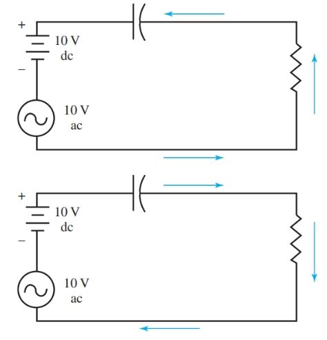
Figure 2. The ac generator and dc source are connected in series to the RC circuit.
Notice that a voltage appears across R due to the charge and discharge of C. The output of this circuit, then, taken from across R, represents only the ac component of the incoming signal voltage. See Figure 3.
The dc component is blocked by capacitor C. There is little phase shift between the input and output waves because the value of R is chosen as ten times or more the value of the reactance of C at the input voltage frequency. When this ratio of resistance to reactance is maintained, the phase shift does not affect the waves.
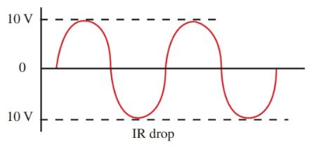
Figure 3. The voltage across R is the result of the charge-discharge current and represents the ac component of the signal.
Bypassing
At times it is necessary to create a voltage drop across a resistor resulting from only the dc component of a signal voltage. This is done by bypassing an ac signal or voltage around a resistance. This bypassing can be accomplished using a capacitor.
Part A of Figure 4 shows two 1500-ohm resistors joined to a source of 10 volts dc. Total resistance equals R1 + R2, or 3000 ohms. The current in the circuit is:
\[I=\frac{E}{R}=\frac{10V}{3000\Omega }=3.3mA\]
The voltage drop across each resistor is:
$\begin{align} & {{E}_{{{R}_{1}}}}=I*R=0.0033A*1500\Omega =5V \\ & {{E}_{{{R}_{2}}}}=I*R=0.0033A*1500\Omega =5V \\\end{align}$
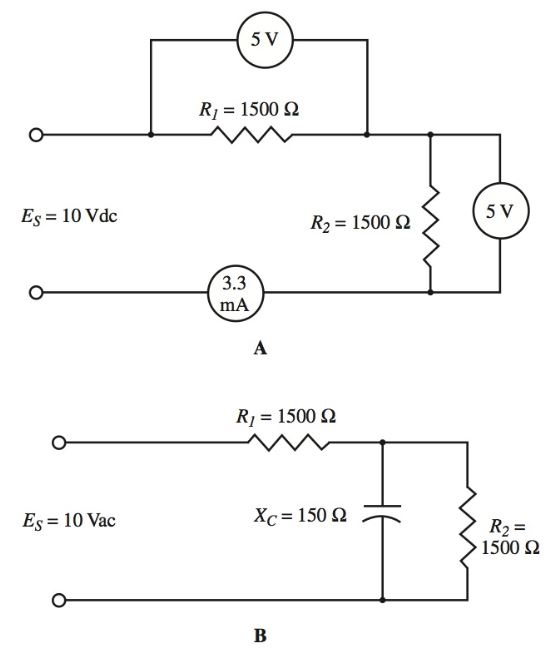
Figure 4. A–A dc voltage produces equal drops across R1 and R2. B–The voltage drop across R2 is held constant by bypassing the ac component.
- Connect a 10-volt ac source now and an ac voltage will appear across both resistors. But we wish to bypass this ac component around R2. To do this, connect a capacitor that has low reactance to the ac voltage in parallel with R2.
- If the reactance of C is one-tenth of resistance R, the greater part of the varying current will flow through C and not through R. Use the values given in part B of Figure 4. C has a 150-ohm reactance to the ac frequency. This reactance is one-tenth the 1500-ohm value of R2. For the most part, the impedance of R2 || XC (R2 and XC in parallel) can be given as a value of 150-ohms. Voltage distribution around this circuit can be measured or computed.
- Total resistance for the entire circuit equals R1 + (R2 || XC) or 1650 ohms. R2 || XC represents one-eleventh of the total resistance to the alternating current.
- Because voltage drop is a function of resistance, ten-elevenths of the voltage appears across R1 and only one-eleventh across R2 || XC. The applied ac voltage is 10 volts, so:
$\begin{align} & {{E}_{{{R}_{1}}}}=9.1V \\ & and \\ & {{E}_{{{R}_{2}}}}=0.9V \\\end{align}$
- If a 10-volt dc voltage is connected in series with the 10-volt ac voltage for the combined input voltage, the dc voltage will divide equally between R1 and R2. The dc voltage will drop five volts across each resistor. C is an open circuit for a direct current.
- The ac voltage divides in the ratio calculated earlier. Most of this voltage appears across R1. The voltage across R2 remains fairly constant due to the bypass capacitor action.
To summarize, choose a capacitor that will form a low-reactance path around a resistor for currents of chosen frequencies. This produces a voltage across one resistor that is almost entirely dc.
Low-Pass Filters Working
At times, a filter is needed that will pass low frequencies, yet decrease the high-frequency currents. This filter is called a low-pass filter.
A low-pass filter circuit always has a resistance or an inductor in series with the incoming signal voltage. It also has a capacitor in shunt or across the line, Figure 5.
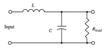
Figure 5. A low-pass filter circuit.
- As the frequency is increased, the reactance of L increases so that a larger amount of the voltage appears across L.
- Also as the frequency increases, the reactance of C decreases. The capacitor thus provides a bypass for the higher frequency currents around the load resistance R.
- Because of the increased reactance of the inductor and decreased reactance of the capacitor at high frequencies, the higher frequencies appear only in small amounts across the load.
- Low frequencies develop higher voltages across the load. Low frequencies are passed, high frequencies are rejected.
High-Pass Filters Working
The opposite to the low-pass filter is the high-pass filter. High-pass filters pass chosen high-frequency current and reject low-frequency currents.
The filter circuit includes a capacitor in series with the incoming signal voltage and an inductance shunt across the line, Figure 6.
- As the frequency increases, XL increases and a higher voltage is developed across L and R in parallel.
- As frequency increases, XC decreases, providing a low- reactance path for high-frequency signals.
- Low frequencies are shunted or bypassed around the load R by the low reactance of L at low frequencies.
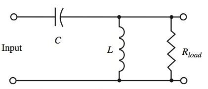
Figure 6. A high-pass filter circuit.
To improve the filtering action of both low- and high-pass filters, two or more sections are often joined. These sections are named according to the circuit makeup. Figure 7 illustrates the schematic drawings and the names of several types of filters.
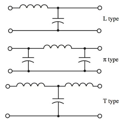
Figure 7. Filter circuits can be named according to circuit configuration.
Tuned Circuit Filters
Series and parallel resonant circuits are said to be acceptor or reject circuits. These tuned circuits can be used as filters because they are able to give a maximum response at their tuned resonant frequency.
In Figure 8, a series resonant circuit is used as a band-pass filter. A band-pass filter accepts only currents near its resonant frequency.
In Figure 9, the series resonant circuit is shunted across, or parallel to, the load. This provides a low impedance path around currents at resonant frequencies (bypassing the load). In this case, the filter would respond as a band-reject filter. Band-reject filters reject a specific band of frequencies.
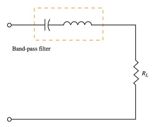
Figure 8. The series tuned circuit used as a bandpass filter.
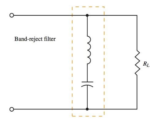
Figure 9. A series tuned circuit arranged as a band- reject filter.
The circuits in Figure 10 use a parallel tuned circuit. The effect of the parallel tuned circuit is the opposite of the series tuned circuit.
When the tank circuit is in series with the incoming currents, it provides maximum impedance and rejects the frequencies around its resonant frequency.
When the tank circuit is shunted across the load, it causes the maximum response across the load at resonance. Frequencies other than resonance are bypassed because of the decreased impedance of the shunt tuned tank circuit.
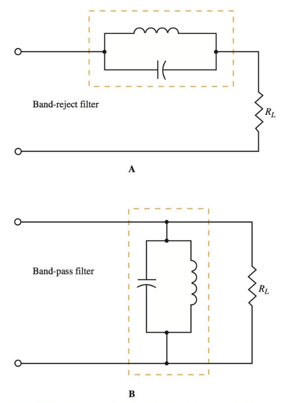
Figure 10. A–The parallel tuned circuit as a band-reject filter. B–The parallel tuned circuit as a band-pass filter.
Combinations of both series and parallel tuned circuits can be used to provide sharper cutoff and greater attenuation.