The article provides an overview of serial and parallel ports used in computers, discussing how various input/output (I/O) devices connect to a system through different port types and connectors. It also highlights key characteristics, uses, and differences of common connection interfaces such as USB, FireWire, PS/2, and legacy ports like RS-232 and LPT.
Lesson Objectives
- Identify and compare I/O ports.
- Identify the characteristics of connection interfaces.
- Identify connector types and associated cables.
- Identify the appropriate connector or cable for various hardware components.
Device Connections
All devices connect to the motherboard in some way. Internally they connect to the PCI slots, PCI express slots, IDE interface, SATA interface, or some other bus system. External devices connect to a computer using Input/ Output (I/O) ports.
I/O ports transmit data via serial or parallel connections that can be manipulated from within the BIOS. I/O ports send and receive data in the form of bits (0s and 1s), which can be transmitted in serial or parallel.
Serial Transmission
Serial transmission refers to the transmission of data down a single wire one bit at a time. Figure 1 illustrates serial transmission.
Among other applications, serial ports are often used to allow a technician to interface with the operating system of a device by typing commands in a terminal window that is spawned by software that communicates with the device through the serial connection.
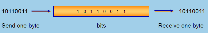
Figure 1: Serial Transmission
Parallel Transmission
Parallel transmission refers to the transmission of x bits across a channel at a time, where x is the number of wires in the channel. Typically, there are eight wires in a channel so one byte of data is sent at a time. Figure 2 illustrates the parallel transmission.
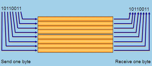
Figure 2: Parallel Transmission
Types of Connectors and Ports
There are many types of external connections that can be made with a computer. Common external connections include serial, parallel, PS/2 for keyboard and mouse, USB, FireWire, and Bluetooth. Keep in mind the following point of clarification regarding connectors and ports.
The term connector is used to describe a physical-mechanical device used to interconnect electronic components or cables; a connector can be either male or female.
The term port is used to describe the logical function associated with a connector; for example, an RS-232 port is accessed via a DB-25 connector and an Ethernet port is accessed using an RJ-45 connector. However, be aware that practitioners (us!) often use the terms connector and port interchangeably.
Serial Connectors
Serial connectors were one of the first types of connectors included with motherboards. During the days of the AT form factor, they were added through a series of jumpers. On ATX motherboards they are built-in.
Serial transmissions are relatively slow because information has to travel one bit at the time down a single wire. Devices like a wired mouse or a dial-up modem are ideal for this type of connection.
Serial connections are characterized by the use of a DB-9 male or a DB-25 male connector. DB references the D shape and the shell size (B), and the number represents the number of pins in the connector. Figure 3 displays a DB-9 connector.

Figure 3: DB-9 Serial Port
Serial Ports
Serial ports are also known as communication or COM ports. They are bidirectional, meaning data can flow in both directions, either sending or receiving data. Serial ports use various pins to send and receive data.
According to How Serial Ports Work, “using the same pins would limit communication to half-duplex, meaning that information could only travel in one direction at a time. Using different pins allows for full-duplex communication, in which information can travel in both directions at once.”
There are up to four COM ports on a computer system: COM1, COM2, COM3, and COM4. Serial ports are also referred to as RS-232 ports; this is because RS-232 is a (particular) standard for serial communication that used to be integrated into almost all computers.
The recommended maximum length of an RS-232 cable is 15 meters. Modern computers usually have USB ports instead of RS-232 serial ports; USB-to-RS-232 converters are used to connect RS-232 peripherals if required. USB ports will be described in detail later in this lesson.
DIN-5 Connector
Older AT style motherboards had only one connection port built-in. It was a DIN-5 connector (also known as a 5-pin DIN connector) and was used to connect the keyboard. Figure 4 shows a DIN-5 connector. When a mouse was used with AT motherboards, it connected through a DB-9 connection, as in Figure 3.
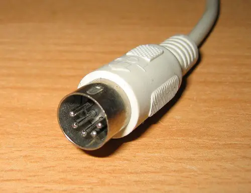
Figure 4: DIN-5 Connector for Keyboard
PS/2 Connectors
When ATX motherboards were introduced, the keyboard and mouse connectors changed to a 6-pin “mini-DIN”, also known as a Mini-DIN-6 connector. The IBM Personal System/2 personal computers came with Mini-DIN-6 connectors for keyboards and mice.
These connectors were called PS/2 connectors (naturally!) Because of IBM PC compatible computers used PS/2 connectors for keyboards and mice, and because the PS/2 connector is a particular type of Mini-DIN-6 connector, the term PS/2 is often used interchangeably with Mini-DIN-6.
PS/2 connectors are still included on many modern motherboards, but USB ports are used much more often nowadays for keyboards and mice.
PS/2 connectors are color-coded to make it easy to plug in the right device. The purple connector is always for the keyboard and the green connector is always for the mouse. The keyboard and mouse are not interchangeable. Figure 5 displays PS/2 connectors.
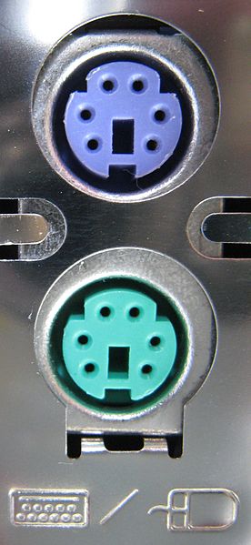
Figure 5: PS/2 Connectors for Keyboard (Purple) and Mouse (Green)
Parallel Ports
Parallel ports on motherboards are used for printers, scanners, and other devices that need high throughput. Many motherboards no longer include parallel ports, because modern peripherals normally use USB connections.
Parallel ports use a DB-25 female connector which transfers two bytes of information at a time over 16 wires, with the remaining 9 wires used for control signaling.
Since there are both serial and parallel port implementations of DB-25, it is important to be able to tell them apart. When looking at the computer, the serial port is always a male connector, and the parallel port is always a female connector.
Parallel ports are also known as LPT ports. There can be up to three of these ports on a motherboard, but nowadays usually zero or one. This port is bidirectional, and the transmission mode for this port can be set in the BIOS.
The IEEE 1284 standard specifies parallel communication between a computer and a connected printer via a parallel cable. As described above, the port on the computer is a DB-25 port, referred to in the 1284 standard as Type A.
Figure 6 displays a DB-25 parallel port. The printer port which connects by a cable to the parallel port of a computer is a 36-pin Centronics port, referred to in the standard as Type B.

Figure 6: DB-25 Parallel Port
Figure 7 displays a Centronics connector. The recommended maximum length of a parallel cable is 4.5 m.
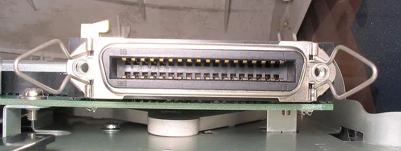
Figure 7: Centronics Connector
Universal Serial Bus (USB)
The Universal Serial Bus (USB) was created to replace the slower serial options that predate it. USB uses four wires. Two wires are used to provide power, and data is transferred over a twisted pair of wires. USB ports are shown in Figure 8.
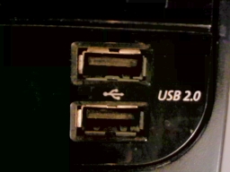
Figure 8: USB Ports
USB has several advantages over its serial predecessors, including:
- It is host-based, meaning that devices can only communicate with each other if they are connected to the same computer;
- One USB port can connect up to 127 devices, either directly or by way of USB hubs;
- An individual USB cable length is limited to a maximum of 5 meters, but when used with hubs, connected devices can be up to 30 meters away (using six cascading cable runs);
- USB provides its own power source to devices with two wires: one wire providing up to 5 V and 500 mA of power and the second wire is a ground.
Note: USB internal power is inadequate for many devices requiring a USB connection. USB power was designed only to be used with low-power devices, such as mice or keyboards. For example, printers and external hard drives must provide their own power source and draw little power from the USB bus. There are devices, though, such as USB-powered LCD monitors, that use two USB connections to a computer to provide sufficient power without the need for an AC power supply.
USB devices are hot-swappable, meaning that one can connect them and disconnect them at any time without restarting the computer. When the host computer enters a power-saving mode, the host can put connected USB devices into sleep mode to save power.
Windows 98, 2000, XP, Vista, 7, and 8 operating systems have built-in USB compatibility. Windows 95 and Windows NT 4.0 do not support USB since they were created before USB technology was available.
To avoid confusion and prevent electrical overloads, the USB standard specifies an A connector and a B connector. Only an A-type port provides power.
The A connector, shown in Figure 9, is a flat connector that sends the data upstream. The B connector has a square shape with a “house-shaped top” on one edge and is used as the downstream or receiving end of the cable. The A connector is found on the back of the computer and the B connector is found on the external device.

Figure 9: Type A and Type B USB Connectors
USB Standards
USB has iterated through several versions over the years. The original USB 1.0 had a maximum bandwidth of 1.5 Mb per second. USB 1.1, or low-speed USB, added power and increased the bandwidth to 12 Mb per second. USB 2.0, or high-speed USB, increased the bandwidth to 480 Mb per second making it 40 times faster, so it is better suited for multimedia and external storage applications.
USB 2.0 is backward compatible: a USB 2.0 device can be connected to a USB 1.1 port, but the connection speed slows down to USB 1.1 speed. However, USB 1.1 will not work in a USB 2.0 connection. USB 3.0 increased the maximum bandwidth to 5 Gb per second, making it one of the fastest connections today.
USB Cable Lengths
It is important to be familiar with the acceptable range of cable lengths for USB. High-speed devices support maximum cable lengths of 5 meters, while low-speed devices support a maximum cable length of 3 meters. These lengths can be extended with the use of powered hubs. USB connections are used for any number of devices, including cameras, scanners, and barcode readers.
FireWire
FireWire, also known as IEEE 1394, was first developed by Apple computers in 1995. It was intended as a high-speed, bidirectional 400 Mbps serial transfer technology, for scanners, camcorders, and digital cameras.
USB 1.1 and FireWire were released at about the same time – USB on PC devices and FireWire on Apple devices. PC users, of course, wanted to take advantage of the higher speed of FireWire, so manufacturers created a special adapter card that would plug into the PCI slots common to PCs.
Another advantage of FireWire is that it forms a peer-to-peer connection, meaning that any two FireWire devices can be plugged together directly and communicate with each other without a computer in the middle. FireWire slots are now included on most motherboards.
There are 4-conductor and 6-conductor FireWire implementations. A 6-conductor FireWire device can draw power through the cable just as in the case of USB; two power conductors are included, supplying a maximum of 30 volts and 1.5 amps to a connected device.
Low power consumption devices, such as digital cameras, can draw power from a 6-conductor FireWire port; high power consumption devices, such as external hard drives, may require a separate AC power source.
A FireWire cable has either two or three pairs of twisted wires that carry data. Like USB, FireWire devices are hot-swappable. Figure 10 displays 4-conductor and 6-conductor FireWire connectors.

Figure 10: 4-Conductor (Left) and 6-Conductor (Right) FireWire Connectors
Figure 11 displays 6-pin FireWire ports. The recommended maximum length for a FireWire cable is 4.5 m.

Figure 11: 6-Pin FireWire Ports
After the release of USB 2.0, IEEE 1394b, or FireWire 800, was released, using nine conductors and increasing the transfer speed to 800 Mbps. The full specification enables rates up to 3200 Mbps over optical connections. Future versions of FireWire are expected to support rates up to 6.4 Gbps.
Bluetooth
Bluetooth is one of the newest connection types and creates a wireless personal area network (PAN). Printers, digital cameras, laptops, mobile phones, PCs, and video game consoles can connect and communicate with each other using Bluetooth. This technology uses an unlicensed, short-range radio frequency to provide a secure connection.
Hands-free audio connections in a car, as well as in-ear headsets, typically rely on Bluetooth technology. Bluetooth has been supported on PCs since Windows XP Service Pack 2 and on Apple computers beginning with Mac OS X version 10.2. Figure 12 displays a Bluetooth earpiece for hands-free mobile phone communication.

Figure 12: Bluetooth Earpiece
Figure 13 shows the official Bluetooth logo, used to indicate to consumers the presence of Bluetooth technology on a device.

Figure 13: Bluetooth Logo
Bluetooth is a protocol that was created mainly for low-power consumption. This wireless (radio frequency) standard provides connectivity for devices that contain low-cost transceiver microchips and have a short range.
Bluetooth radios are divided into three classifications:
- Class 1 provides 100 mW of power and about a 100-meter range.
- Class 2 provides 2.5 mW of power with a range of about 10 meters.
- Class 3 provides 1 mW of power and a range of about 1 meter and is common on our mobile phones.
Bluetooth has three possible transmission speeds:
- Bluetooth 1.1 has a maximum throughput of 721 kb per second.
- Bluetooth 2.0 has a maximum throughput of 2.1 Mb per second.
- Bluetooth 3.0 has a maximum throughput of 24 Mb per second.
eSATA
External SATA (eSATA) is another one of the newest interface types. It supports a maximum cable length of 2 meters and transfer speeds of up to 6 Gbps. Like USB and FireWire, it is hot-swappable. A common use of eSATA is to connect external hard drives. Figure 14 displays two eSATA sockets.

Figure 14: eSATA Sockets
Figure 15 displays two eSATA connectors.

Figure 15: eSATA Connectors
I/O Port Comparison
For the CompTIA 220-801 A+ certification exam, it is important to know the name of each I/O technology, the associated standard, the type of bus it uses, the maximum cable length, the maximum transfer speed, whether power can be provided, and the number of devices it can support. Table 1 summarizes this information.
Table 1: I/O Technology Comparison
| Name | Standard | Bus | Max Length | Max
Transfer Speed |
Power Provided | Devices per Channel |
| Serial | RS-232
DB-9 male DB-25 male |
Serial | 15 m | 460 Kbps | No | 1 |
| Parallel | IEEE 1284
DB-25 female |
Parallel | 4.5 m | 20 Mbps | No | 1 |
| USB | USB 1.1
USB 2.0 |
Serial | 3-5 m | 12 Mbps
480 Mbps |
Yes | 127 |
| FireWire | IEEE 1394
IEEE 1394b |
Serial | 4.5 m | 400 Mbps
800 Mbps |
Yes | 63 |
| eSATA | eSATA | Serial | 2 m | 6 Gbps | No | 1 |
| Bluetooth | IEEE 802.15.1 | Wireless | Class 1: 100 m
Class 2: 10 m Class 3: 1 m |
24 Mbps
(Bluetooth 3.0) |
No | 7 |
ATX System Board I/O Connections
To see many of the ports we have discussed in context, Figure 16 displays an example of an ATX motherboard I/O port arrangement. Be able to recognize and name each of the connectors.

Figure 16: ATX Motherboard Connectors
Serial and Parallel Ports Key Takeaways
In this lesson, serial and parallel transmissions were described. The major types of serial and parallel ports were introduced, as well as the standards associated with them.
Maximum cable lengths and transfer speeds were detailed for the various technologies, and the built-in power source, if any, was described for each of these technologies.
The characteristics of each I/O technology were compared, and it was shown how the ports integrated into an ATX motherboard.