The article provides an overview of computer form factors, cases, and power supplies, highlighting their compatibility and role in system configuration. It also covers identifying motherboard properties, power supply types and connectors, and selecting appropriate hardware based on system requirements.
A computer technician must be able to differentiate among the various form factors available versus the type of case being used. The computer case holds all of the system components starting with the motherboard (or system board) and power supply. All three must use the same form factor. Computer form factors, cases, and power supplies are introduced in this lesson.
A computer technician must also be able to determine whether a power supply is adequate based on the configuration of the computer and the components installed.
Lesson Objectives
- Identify the distinguishing properties of a motherboard.
- Differentiate between computer form factors.
- Identify power supply connectors.
- Identify the voltage for each colored power supply wire.
- Select an appropriate power supply based on a given scenario.
Computer Form Factor
In the early days of computers, every manufacturer had its own proprietary hardware. When a computer was purchased from a manufacturer, one was locked into a specific type of motherboard, processor, memory, hard drive, and every other component.
The term computer form factor describes the size, shape, and general makeup of several of the key base components used in computers.
There are three main components that must have the same form factor:
- Case – houses the hardware components of the computer system
- Motherboard – The main circuit board of the computer system; all system components are plugged into the motherboard
- Power supply – Provides power to the motherboard and all other installed hardware components
Table 1 describes the most common form factors. Differences in form factors include the variation in size and expansion capabilities.
Table 1: Most Common Form Factors
| Form Factor | Size | Usage |
| AT (Advanced Technology)
1980-1990 |
12 X 11-13 in | Obsolete, superseded by ATX. |
| ATX (Advanced Technology eXtended)
The mid 1990s |
12 X 9.6 in | Created by Intel in 1995. It is the most common form factor. |
| Micro-ATX | 9.6 X 9.6 in | A smaller variant of the ATX form factor. Compatible with most ATX cases, but has fewer slots than ATX. Very popular for desktop and small form factor computers. |
| Mini-ATX | 5.9 X 5.9 in | Designed for mobile CPUs with lower power requirement and less heat generation. |
| BTX (Balanced Technology) | 12.8 X 10.5 in | A standard proposed by Intel as a successor to ATX in the early 2000s. |
| DTX | A variation of ATX specification designed especially for small form factor PCs. | |
| Mini-ITX
2001 |
6.7 X 6.7 in | A small, highly-integrated form factor designed for small devices such as thin clients and set-top boxes. |
| Nano-ITX
2003 |
4.7 X 4.7 in | Targeted at smart digital entertainment devices such as personal video recorders (PVRs), media centers, car computers, and thin devices. |
| Pico-ITX
2007 |
3.9 X 2.8 in | Used in custom media center computers, car computers, and small home servers. |
As computer systems were being developed in the 80s and early 90s, the Advanced Technology (AT) form factor was used. In the mid-90s as computers were becoming faster and new technologies were being developed, the Advanced Technology eXtended (ATX) form factor was created.
The ATX added built-in functionality for keyboards, mice, printers, and much more. It is still a very popular form factor in use today. In recent years, many variations of the ATX have become available, including micro-ATX and mini-ATX.
The Balanced Technology eXtended (BTX) form factor was created in the early 2000’s as a replacement for ATX but was never very successful. The same can be said for the DTX form factor. Although one can find the BTX and DTX form factors today, they are not widely used.
The newest form factor is the ITX or Integrated Technology eXtended. It is found in three versions: the Mini-ITX, the Nano-ITX, and the Pico-ITX.
Types of Computer Cases
Cases on the market today vary in size and even color. All cases perform the same basic functions–to house the system components and provide cooling. Features such as colored lights and transparent sides have nothing to do with the case’s functions – these features simply make the case more attractive.
There are three important considerations when selecting a case:
- The case should accommodate all components and the fans required for keeping components from overheating.
- The case should provide good airflow. Cooling turns out to be more efficient with the case sealed rather than open. For good airflow and efficient cooling, the flow into the case should at least match the flow of air coming out (positive airflow).
- The case should be easily sealed. With a sealed case, one minimizes dust reaching the internal components while optimizing cooling. Maintaining positive airflow minimizes dust entering the case.
Cases can be distinguished by physical dimension. Figure 1 illustrates the various types of cases. The minitower is sometimes called the shuttle form factor and was often used with portable computers. Ninety percent of cases fall in the midsize tower category. Full-size towers are used with servers and multi-bay systems.
Desktops are less popular because the footprint of the system takes up more space and they are difficult to maintain. Slimline desktops are fixed-configuration versions of the desktop, with smaller vertical dimension, and they are not upgradeable.
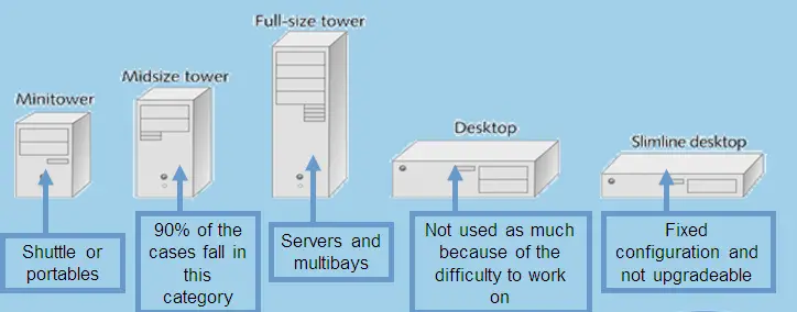
Figure 1: Types of cases
Types of Motherboards
The motherboard is also known as the mainboard or system board. It is a printed circuit board which means that it electrically connects all of the electronic components. The motherboard contains a socket which holds the central processing unit, or CPU.
The CPU processes the data and the instructions for the entire computer system. Deciding on the type of motherboard is usually the first step when building a computer. Different types of motherboards support different CPU’s and have different expansion capabilities to add hardware components down the road.
The motherboard must fit in the case. There are holes in the motherboard that align with the holes in the case. There are also holes in the case that align with the ports of the motherboard. Ports are physical connectors that allow the connection of devices such as a mouse or printer.
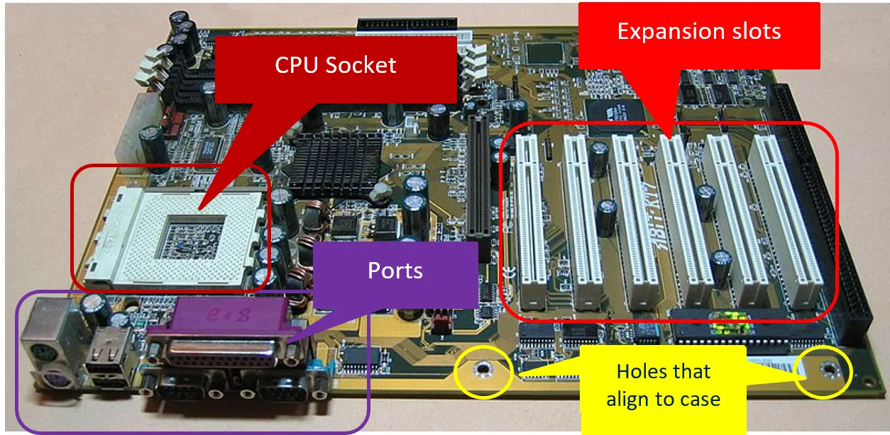
Figure 2: ATX motherboard
Several motherboards are pictured in Figure 3. When a case is labeled as ATX, for example, the basic layout and configuration of the motherboard is the same. For this reason, a case can hold smaller versions of the same form factor. So an ATX case can hold an ATX, micro-ATX, or mini-ATX motherboard, for example, but a micro-ATX case could not support a full-size ATX motherboard.
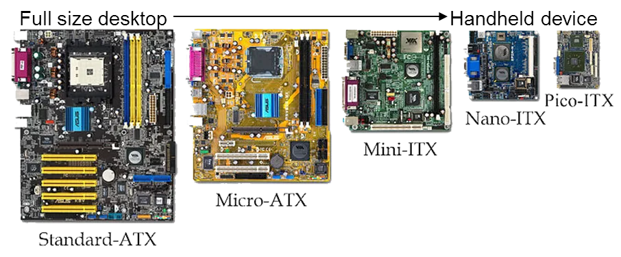
Figure 3: Comparison of computer motherboard form factors
Computer Power Supplies
The backside of every power supply looks essentially the same. Each has a fan for cooling. For an ATX form factor, the fan is always taking the air out of the computer. Conversely, an AT form factor is pulling air into the case. A power switch turns the power supply on and off. An external power connection accommodates the power cord.
Many power supplies have a dual voltage selector that allows the choice of 110 volts for the US and Canada or 220 volts for England, Greece, or China, for example. For more information on foreign voltage by country, review the Foreign Voltage Guide by Country.
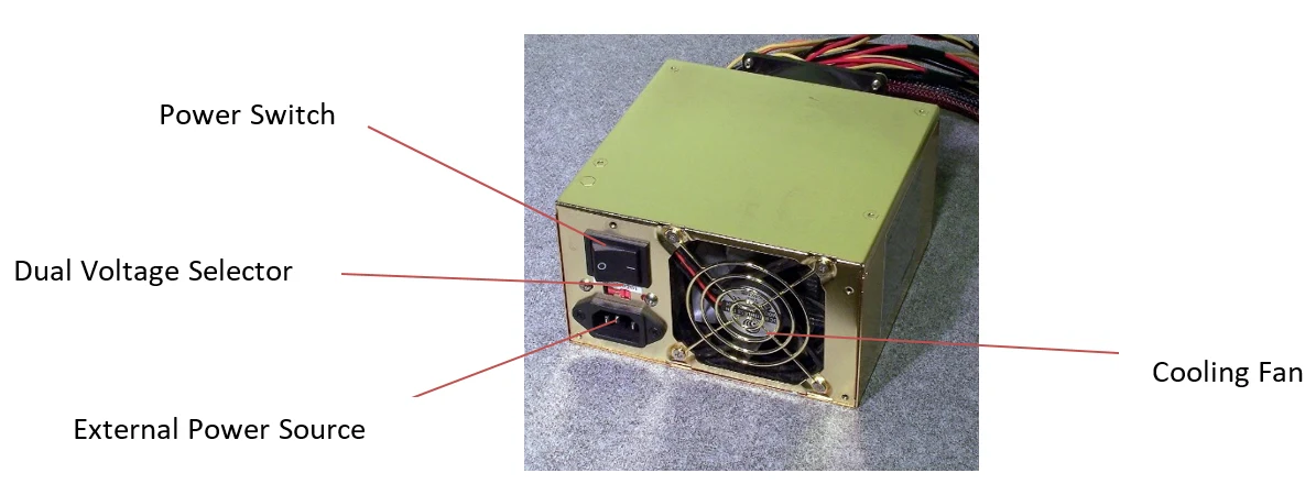
Figure 4: PC Power Supply
There are several types of power supplies. A Desktop power supply like the one pictured in Figure 4 is installed internally within the case. Laptops and portable devices usually have an external power supply as shown in Figure 5.
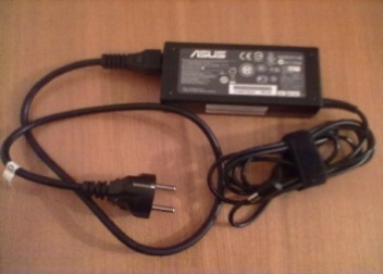
Figure 5: Laptop power supply
Some higher-end computers and most servers have redundant power supplies which protect the computer from going down if the primary power supply fails; this is known as fault tolerance.
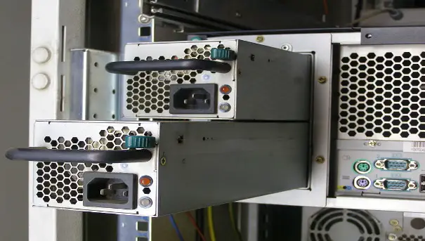
Figure 6: Server power supply
Troubleshooting Power Supplies
An A+ technician is not certified to open or repair a power supply. If something goes wrong with a power supply, the options are to take it to an authorized repair service or to simply replace it.
Common power supply problems for home users can usually be traced back to the power switch being off or the wrong voltage selected. Some power supplies have a light indicating when the power is on. A blinking light indicates there is not enough voltage coming into the power supply.
Power Connectors
The type and number of connectors on a power supply is dependent on the wattage of the power supply. In general, higher wattage is associated with a greater number of connectors which support more installed hardware components. It is important to learn about each of these connectors and the associated wattage.
Motherboard Power Connectors
Older ATX motherboards were powered by the 20-pin P1 connector. This connector provided +3.3 volts, +5 volts, +12 volts, and -12 volts and could power expansion cards installed in PCI expansion slots.
Today, the 24-pin P1 connector is the main motherboard connector. The extra four pins provide +12 volts, +5 volts, and +3.3 volts and support PCI Express expansion slots.
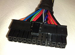
Figure 7: 24-pin ATX power connector
When processors (CPUs) began to require more power, the 4-pin motherboard auxiliary connector was added. The connector on the motherboard was located near the CPU socket. The four pins auxiliary connector provided an additional 12 volts of power.
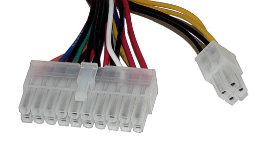
Figure 8: 20- and 4-pin power connector
The 20+4 P1 connector has the flexibility to plug in either a 20-pin or 24-pin power connector on a motherboard.
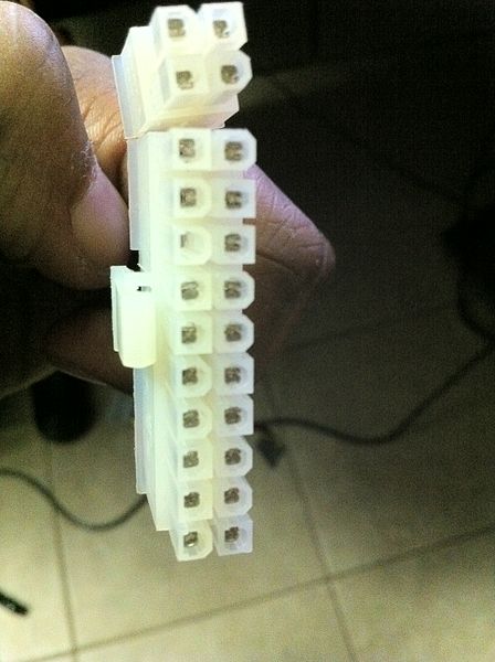
Figure 9: ATX or 20/24-pin connector
If the pin count of a connector on the power supply does not match that of the main power connector on the motherboard, adapters can be purchased to increase a 20 pin to a 24 pin or to decrease a 24 pin to a 20 pin.
Auxiliary Power Connectors
The 4-pin auxiliary connector was later replaced with an 8-pin motherboard auxiliary connector that provided additional amps for the processor. The additional 4-pin and 8-pin connectors provide extra power to motherboards that use a Pentium 4 or higher processor.
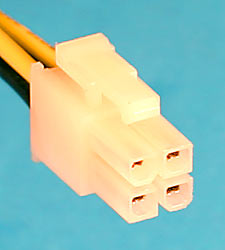
Figure 10: 4-pin auxiliary power connector
In the article, PC Power Supply Cables and Connectors, the various power supply connectors used with computers are described.
The 6- and 8-pin connectors pictured in Figure 11 provide power to the Peripheral Component Interconnect express (PCIe) slots for devices such as graphics cards.
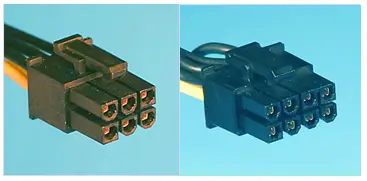
Figure 11: 6- and 8-pin PCI Express connectors
Both of these power connectors provide +12 volts.
Expansion Power Connectors
Every component that is added to a system requires power. Hard drives and other storage devices such as CD-ROM and DVD drives have their own set of power connectors. IDE (or PATA), SCSI, and SATA are the interfaces or standards that describe the connections between the drive and the motherboard (not the drive itself); but the terms IDE, SCSI, and SATA are commonly used to describe the drive itself.
Berg Power Connector
The berg connector is used to provide power to floppy drives. The floppy drive has become obsolete due to the increased storage capacity of devices such as USB or flash drives.
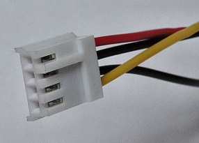
Figure 12: Berg power connector
The Berg power connector provides 12 volts.
Molex Power Connector
One or more hard drives or optical drives (CD, DVD, or Blu-ray) can be installed in a computer. There are two different standards for these drives, and each uses a different power connector. The Molex connector provides power to the older parallel ATA (PATA) standard.
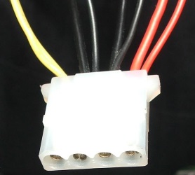
Figure 13: Molex power connector
Molex connectors provide 12 volts.
SATA Power Connector
The faster serial ATA (SATA) standard for hard drives and optical drives uses the SATA power connector.
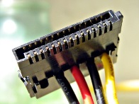
Figure 14: SATA power connectors
SATA power connectors provide 12 volts.
Power Supply Wire Colors
Table 2 describes the association between power supply wires and voltages used to power various hardware components.
Table 2: Power Supply Wire Chart
| Voltage | Wire Color | Use | AT Power | ATX Power | Acceptable Voltage Range |
| +12v | Yellow | Disk drive motors, fans, cooling devices, and the system bus slots | ✔ | ✔ | +10.8 to +13.2 |
| -12v | Blue | Some types of serial port and early programmable ROM | ✔ | ✔ | -10.8 to -13.2 |
| +3.3v | Orange | Most newer CPUs, some types of system memory, and AGP video cards | ✔ | +3.1 to +3.5 | |
| +-5v | Red | Motherboards and earlier CPUs | ✔ | ✔ | +4.5 to +5.5 |
| -5v | White | ISA bus cards | ✔ | ✔ | -4.5 to -5.5 |
| 0v | Black | Ground – Used to complete circuits with the other voltages | ✔ | ✔ |
The wires on a power supply are color-coded to help distinguish the correct voltage (V). The yellow wire provides a +12 V, the blue wire a -12 V, the orange wire a +3.3 V, the red wire a +5 V, the white wire -5 V, and the black wire is the ground.
Electrical Measurements
There are a few terms that need to be understood to properly select the appropriate power supply for a given system.
Voltage measures change in electrical potential energy between two positions and is denoted V. Current is measured in amperes (amps), denoted A, and measures the flow of electricity. Since the resistance (or, by analogy, the “size of the pipe” in reference to fluid flow), denoted R, cannot be changed, this measurement is not as relevant to the calculations involving power supplies. Electrical power is measured in watts, denoted W. It is important to know how much power is needed to run a computer in order to select the appropriate power supply for the computer.
Table 3: Measures used with Electricity
| Unit | Measured in | Water Hose Example |
| Voltage (V) | Volts (V) | Water Pressure |
| Current (I) | Amps (A) | Flow Rate |
| Resistance (R) | Ohms (Ω) | Size of Pipe |
| Electrical Power (P) | Watts (W) | Voltage x Current
P = V x I or W = A x V |
To understand how electricity is measured, think about the flow of water through a water hose:
- The pressure placed on the water source is like voltage.
- The rate of the flow of water through the hose is like current.
- The size of the water hose is the resistance.
The flow of water can be altered by adding more pressure on the water source or by increasing the diameter of the water hose.
For more details on this example, read What are amps, watts, volts, and ohms?
Choosing a Power Supply with Sufficient Wattage
To choose the correct power supply for a PC, a technician needs to know the required wattage. Power supplies are always measured in watts. The number of watts (power) is equal to the number of amps (current) times the number of volts (voltage):
$Power=Current\times Voltage$
In the United States, the AC current on the outlets is 120 volts at 60 Hz. Hertz (Hz) describe the number of times per second the current changes direction. So, for all of the calculations, the number of watts is equal to 120 times the number of amperes (amps).
Here is a summary of the pieces for electrical power calculations:
- The total amount of power required to operate an electrical device measured in watts (W)
- Computed by multiplying volts by amps in a system (A x V = W)
- In the US, residential electrical power from an outlet is 120 V at 60 Hz
It helps to practice calculating the appropriate size of the power supply. For example, if all the current requirements for the components in a computer are added and the sum is 4 amps, then 4 amps is multiplied by 120 volts to get 480 watts; this is the maximum output of the computer. A power supply is not made to run at the maximum output so it is a good idea to add 20% to the maximum. In this case, 20% translates to an additional 96 watts. So a power supply supporting at least 576 watts is required. Power supplies are rated in 50-watt increments. So for this example, a 600-watt power supply would be ideal.
Here is a summary of the example:
A computer draws 4 amps:
- 4 A x 120 V = 480 W (minimum to run PC)
- 480 x .20 = 96 (add 20% to minimum)
- 480 + 96 = 576 W (needed from power supply)
- Power supplies come in increments of 50 watts. So a 600W power supply is required to run this computer.
Note that a 250-watt power supply is a minimum wattage power supply that should ever be put in a computer system.
The power supply calculator will help the technician estimate the power consumption of a desktop computer and select the proper power supply unit for the system.
Determining the Form Factor
How does a technician determine which form factor is in use? First, look at the power connector on the motherboard. If it has a 20- or 24-pin key connector, then it is the newer ATX form factor as shown in Figure 15.
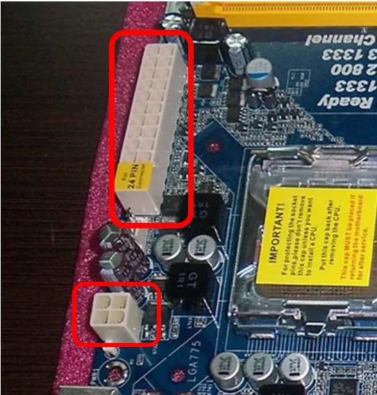
Figure 15: 24-pin and 4-pin power connectors on the motherboard
If there is a 4- or 8-pin auxiliary power connector, it is an ATX, BTX, DTX, or ITX as shown in Figure 15 and 16.
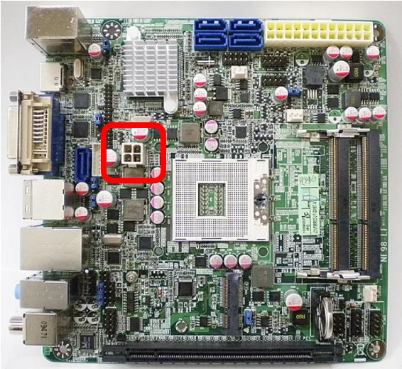
Figure 16: ITX Motherboard
Additionally, look at the ports on the motherboard that show through the back of the case. The ports for the keyboard are usually good indicators.
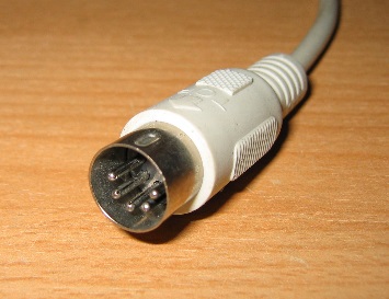
Figure 17: 5 Pin DIN |
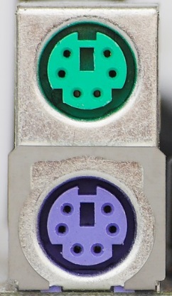
Figure 18: PS2 Ports |
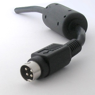
Figure 19: Mini-Din male 4-pin |
If there is only the port for a DIN (or DIN5) connector, then the motherboard has an AT form factor. DIN is an acronym for Deutsches Insitut Normung, an organization that sets standards in Germany. If there are PS/2 ports for the keyboard and mouse mini-DIN connectors, then the motherboard has an ATX form factor. In general, if one finds any ports for keyboard connectors other than the DIN5, then it is safe to assume one is working with an ATX motherboard.
Lastly, the dimensions of the motherboard can be measured to determine the form factor, although this is not as easy as it sounds. The size may vary between models and overlap other form factors. The following can be measured to aid in determining the motherboard type:
- I/O ports on the motherboard
- Size of the motherboard
Computer Form Factors and Power Supplies Key Takeaways
This lesson discussed the various form factors along with the distinguishing characteristics of each. The types of connectors that are needed to connect the power supply to the motherboard and the power connectors that provide power to the hardware components were explained and illustrated. The electrical units used in computer maintenance were described, as well as how to use a power formula to determine the wattage of a power supply required for a particular computer.