This article explains how conductor ampacity, resistance, voltage drop, and power loss are determined in electrical systems, emphasizing the factors that influence safe current-carrying capacity. It also introduces practical methods and formulas used to size conductors, evaluate voltage drop, and assess efficiency and losses in real-world installations.
Conductor Ampacity
The ampacity rating of a conductor is the amount of current it can carry continuously under the conditions of use without overheating or exceeding its temperature rating. General requirements for conductor ampacity can be found in Article 310 of the National Electrical Code (NEC). The most prominent feature of Article 310 is its collection of ampacity tables. These tables set a maximum current value at which the conductor insulation shouldn’t prematurely fail during normal use, under the conditions described in the tables. In general, conductor ampacity is determined by:
Material. Copper is a better conductor than aluminum, and so it can carry more current for a given gauge.
AWG wire size. The smaller the gauge number, the larger the cross-sectional area of the conductor and the more current it can carry.
Type of insulation. All insulated conductors have a maximum operating temperature at which the insulation of the conductor is not adversely affected. A conductor with more heat-resistant insulation will have a higher ampacity rating than one of equivalent size with a lower-insulator temperature rating.
Conductor length. The resistance of a wire increases as its length increases. The listed ampacities in the code tables assume that the length of the conductor will not increase the resistance of the circuit by a significant amount and that the full-rated voltage will be available at the end of the line. For long conductor runs, the wire diameter sizes must be increased above the required rated ampacity of the conductor to keep the amount of line voltage drop to an acceptable level.
Ambient air temperature. The higher the ambient temperature surrounding a conductor, the more difficult it is for the conductor to dissipate heat. When the ambient temperature is above 30°C (86°F), the ampacity rating of the conductor is reduced. NEC Table 310.15(B)(1)(1) gives the ampacity correction factors for situations where the ambient is expected to be higher or lower than 30°C (86°F). For example, the ampacity of a 1/0 AWG, aluminum, type THHN conductor when the ambient temperature is 100°F is found by taking the ampacity from the table and multiplying it by the appropriate correction factor. In this example, the ampacity would be 135 (amperes) × 0.91 (ambient temperature correction) = 122.85 amperes.
Installation conditions. Conductors that are run singly in free air (maximum typical air circulation) will have a higher ampacity rating than a similar conductor that is enclosed with other conductors in a cable or conduit. Adjacent load-carrying conductors affect operating temperature in two ways: the ambient temperature can be raised, and heat dissipation can be impeded. Table 310.15(C)(1) contains the factors for more than three current-carrying conductors. This table states that when the number of conductors in a raceway or cable exceeds three, the ampacities are to be reduced by the appropriate percentage. For example, the ampacity of 12 No. 12 copper THHN conductors installed in one conduit can be found in Table 310-16. In this example, the ampacity (in the table) is 30 amperes and the derating factor for 12 conductors is 50 percent. Therefore, the ampacity would be 30 (amperes) × 0.5 (50%) = 15 amperes per conductor.
The National Electrical Code contains tables that list the ampacity for the approved types of conductor size, insulation, and operating conditions. These tables are a practical source of information that should be referred to for specific circuit installations.
Conductor Resistance
When a conductor carries a current, the conductor’s resistance causes the conversion, into heat, of a portion of the electric energy being transmitted. The resistance of a wire increases as the length of the wire increases, as illustrated in Figure 1. The two wires are of the same material and diameter, but one is twice as long as the other. In this case the longer wire will have twice the resistance of the shorter wire.
Tables indicating wire resistance generally specify the resistance of 1,000 feet of wire at a certain temperature.
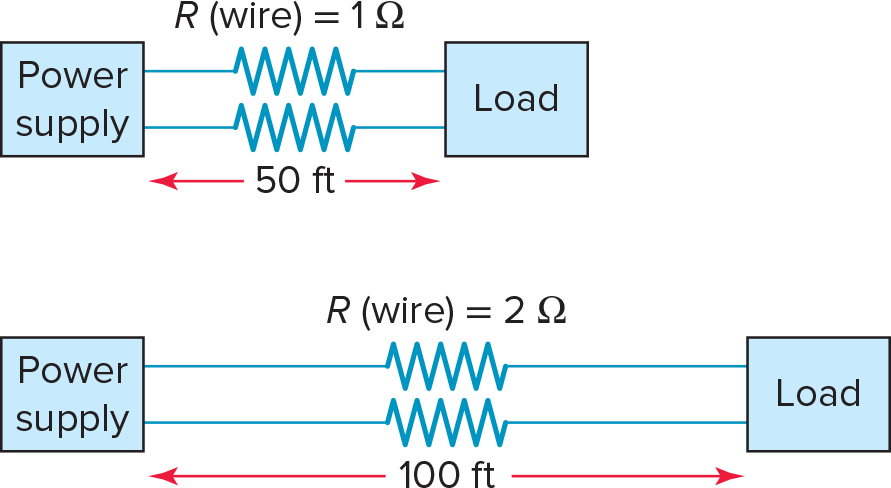
Figure 1. Conductor resistance increases with length.
Resistance Calculation Example 1
The resistance of 1,000 feet of 2 AWG standard annealed copper wire is listed in a wire table as 0.1563 ohms per 1,000 ft at 20°C. What is the resistance of 250 ft of this wire?
Solution:
$$ Resistance = \frac{length(ft)}{1000}\times \textrm{resistance per 1,000 ft}=250\times \frac{0.1563}{1,000}=0.0391\Omega$$
The larger the diameter of the conductor, the lower is its resistance. Large conductors allow more current flow with less voltage drop or loss. For example, a wire with a larger cross-sectional area than another wire has a lower resistance for a given length. For example, shown in Figure 2, the resistance for 1,000 feet of 10 AWG solid copper wire is 1.21 ohms, compared to 3.07 ohms per 1,000 feet for a smaller solid 14 AWG copper wire.
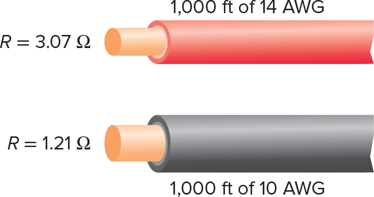
Figure 2. The larger the diameter, the lower the conductor resistance.
The resistance of a conductor varies with temperature. For copper and aluminum conductors, the higher the temperature, the higher the resistance. The two factors that determine the operating temperature of a conductor are the temperature of the surrounding air space (ambient temperature) and the amount of current flow through the conductor.
The physical condition of the conductor and/or connection will also affect resistance. A partially cut or nicked wire will act like smaller-diameter wire, with high resistance in the damaged area. Broken strands in the wire, poor splices, and loose or corroded connections also increase resistance.
Different materials have different atomic structures, which affect their ability to conduct electrons. Aluminum wire, because it is not as good a conductor as copper, has an ampacity approximately equal to that of copper wire two-gauge sizes smaller. For example, 12 AWG aluminum wire has about the same ampacity as 14 AWG copper wire.
Line Voltage Drop and Power Loss
The resistance of the power source line conductors is normally low when compared to that of the load. In most instances, the conductors are treated as being ideal or perfect conductors of electricity. As a result, they are said to have zero resistance. In this case, the voltage value of the source is the same as that across the load, as illustrated in Figure 3.
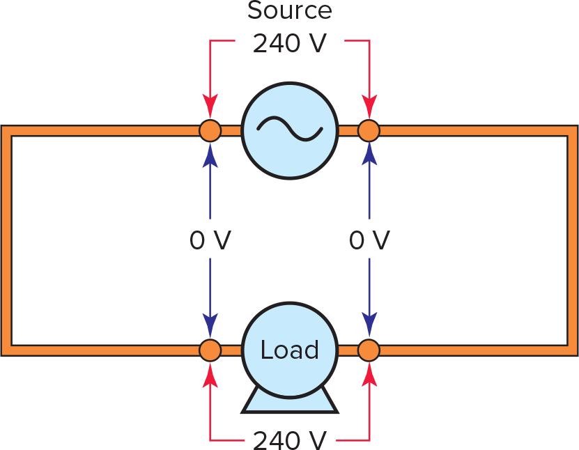
Figure 3. Zero-line voltage drop.
In some circuits, the resistance of the conductors is important and must be taken into account. This is often the case where the load is located some distance from the voltage source—such as hundreds of feet or more. In this type of circuit, the voltage at the load can be significantly less than what appears at the energy source. When this is the case, the line voltage drop is the difference between the operating voltages of the source and that of the load, as illustrated in the circuit of Figure 4. In this example, the supply voltage is 240 V, while the voltage at the load is 230 V, resulting in a line voltage drop of 10 V.
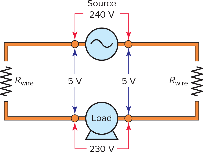
Figure 4. Determining line voltage drop.
Excessive voltage drops result in wasted power and energy. Any voltage that drops between the supply and the equipment is lost to the equipment and, in some applications, can seriously affect the operation of the equipment. As an example, a substantial loss in voltage to a motor can cause a reduction in motor horsepower, increased operating costs, increased motor heat buildup, and reduced motor life expectancy.
When sizing circuit conductors for extremely long circuit runs, the expected voltage drops are estimated before the installation. If necessary, wire diameter sizes are increased above the size required by ampacity to keep the line voltage loss within acceptable limits.
While the NEC does not have requirements for voltage drop, it recommends limiting the voltage drop on branch circuit conductors to a maximum of 3 percent and a total maximum of 5 percent for feeder and branch circuit combined.
Voltage Drop Calculation Example 2
The single-phase voltage at the source and load of an operating branch circuit installation is measured and found to be 120 V and 118 V, respectively. Determine the amount and the percentage of the voltage drop.
Solution:
$$ E_{VD}=E_{source}-E_{load}=120V-118V=2V $$
$$ \textrm{% Voltage Drop}=\frac{E_{source}-E_{load}}{E_{source}}\times 100=\frac{2V}{120V}\times 100=\textrm{1.67%} $$
The voltage drop across a wire is directly proportional to the resistance of the wire and the amount of current it is carrying. The voltage drop can be calculated according to Ohm’s law as follows:
$$ E_{VD}=I\times R_{wire} $$
Voltage Drop Example 3
The current flow through a DC circuit is calculated and found to be 11 amps. What would the expected line voltage drop be if the conductors supplying power to the load have a combined total resistance of 0.2 ohms?
Solution:
$$ E_{VD}=I\times R_{wire}=11A\times 0.2\Omega =2.2V $$
Resistivity (K) is a constant, which is related to a wire’s resistance per circular mil-foot (Figure 5). The resistivity of copper and aluminum wire is different, and both increase as the temperature increases. Table 1 lists the typical values of resistivity (K) for copper and aluminum at three different temperatures. The K values listed are approximate and will vary slightly, depending on the temperature and method used in determining K.
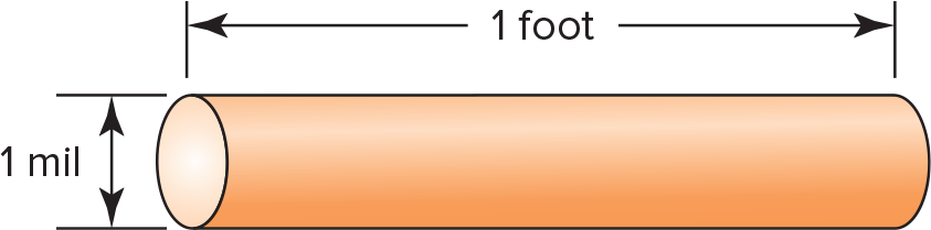
Figure 5. Circular mil-foot.
|
Resistivity K (ohms per circular mil-foot) |
|||
| 25°C | 50°C | 75°C | |
| Copper | 10.8 | 11.8 | 12.9 |
| Aluminum | 17.0 | 19.0 | 21.2 |
Table 1. Resistivity of Copper and Aluminum
The resistance of a given length of a particular size of copper or aluminum wire can be calculated using the resistivity or K factor in the following wire resistance formula:
$$R=\frac{K\times L}{cmil}$$
Where
R = total resistance of the wire in ohms
K = resistivity in ohms per circular mil-foot
cmil = circular mil area of the wire
Resistance Calculation Example 4
What is the resistance of a 2,000-ft length of copper wire that has a cross-sectional area of 10,380 cmils? Assume a temperature of 75°C and a resistivity of 12.9 ohms per circular mil-foot.
Solution:
$$R=\frac{K\times L}{cmil}=\frac{12.9\times 2,000}{10,380}=2.48\Omega $$
The wire resistance formula is transposed or rearranged to determine K, L, or cmil as follows:
$$K=\frac{R\times cmil}{L}$$
$$L=\frac{R\times cmil}{K}$$
$$cmil=\frac{K\times L}{R}$$
Conductor Length Calculation Example 5
The resistance between the two ends of a length of 12 AWG copper wire (cross-sectional area of 6,530 cmils) is measured and found to be 0.8 ohm. Using a K of 12.9, calculate the approximate length of the wire.
Solution:
$$L=\frac{R\times cmil}{K}=\frac{0.8\times 6530}{12.9}=405ft$$
At times it is necessary to compute voltage drop of an installation when the length, size of wire, and current are known. For single-phase systems the following formula is used:
$$ E_{VD}\textrm{single phase}=\frac{K\times I\times L\times 2}{cmil}$$
Where
EVD = voltage drop in volts
K = resistivity in ohms per circular mil-foot
cmil = circular mil area of the wire
L = length in feet from the beginning of the circuit to the load
For three-phase systems, a slightly different formula is used to calculate the voltage drop. The K × I × L is multiplied by $\sqrt{3}$, or 1.73, instead of 2 as follows:
$$E_{VD}\textrm{single phase}=\frac{K\times I\times L\times 1.732}{cmil}$$
Voltage Drop Example 6
A 240-V, single-phase circuit is being used to supply power to an electric water heater. The distance of the circuit from the panel to the load is 85 ft, the load current is 14 amperes, and the cross-section area of the 12 AWG wire is 6,530 cmils. Determine the approximate circuit voltage drop and the percentage voltage drop using a K of 12.9 ohms per circular mil-foot at 75°C.
Solution:
$$ E_{VD}=\frac{K\times I\times L\times 2}{cmil}=\frac{12.9\times 14\times 85\times 2}{6530}=4.70V$$
$$\textrm{Voltage Drop}=\frac{E_{VD}}{E_{source}}\times 100=\frac{4.70V}{240V}\times 100=\textrm{1.96%}$$
The single-phase voltage drop formula is transposed or rearranged, as follows, to determine the minimum cmil size conductor that must be installed to remain below a specified amount of voltage drop value:
$$ cmil=\frac{K\times I\times L\times 2}{E_{VD}}$$
Conductor Sizing Example Example 7
Find the size of copper wire (use a K factor 12.9) required to carry a load of 45 amperes at 240 volts a distance of 500 feet with 2 percent voltage drop. Use Table 2 to determine the closest minimum size acceptable.
Solution:
$$ E_{VD}=240V\times \textrm{2%}=4.8V$$
$$ cmil=\frac{K\times I\times L\times 2}{E_{VD}}=\frac{12.9\times 45\times 500\times 2}{4.8}=\textrm{120,938 mils}$$
Referring to Table 2, it will be found that this size lies between 1/0 AWG and 2/0 AWG, so 2/0 AWG would be the wire size selected.
| AWG | Diameter (in.) | Area (cmil) |
| 18 | 0.0403 | 1,624 |
| 16 | 0.0508 | 2,581 |
| 14 | 0.0641 | 4,109 |
| 12 | 0.0808 | 6,529 |
| 10 | 0.1019 | 10,380 |
| 8 | 0.1285 | 16,510 |
| 6 | 0.1620 | 26,250 |
| 4 | 0.2043 | 41,740 |
| 2 | 0.2576 | 66,370 |
| 1 | 0.2893 | 83,690 |
| 0 (1/0) | 0.3249 | 105,560 |
| 00 (2/0) | 0.3648 | 133,079 |
| 000 (3/0) | 0.4096 | 167,772 |
| 0000 (4/0) | 0.4600 | 211,600 |
Table 2. AWG Gauge Number versus Diameter and Circular Mil Area
The single-phase voltage drop formula is transposed or rearranged, as follows, to determine the maximum length (distance) from the source to the load for a specified amount of voltage drop value:
$$ L=\frac{cmil\times E_{VD}}{2\times K\times I}$$
Conductor Length Example 8
A 240-V single-phase circuit is to provide power to a load. Determine the maximum distance of the circuit from the power supply to the load if the conductor size is 6 AWG, the load current is 30 amperes, and the maximum voltage drop permitted is 1 percent. (Use a K factor of 12.9.)
Solution:
6 AWG area (from Table 2) = 26,250 cmils
$$ E_{VD}=240V\times \textrm{1%}=2.4V$$
$$L=\frac{cmil\times E_{VD}}{2\times K\times I}=\frac{26,250\times 2.4}{2\times 12.9\times 30}=81.4ft$$
Current flow through a conductor also causes a power loss, in the form of heat, due to the conductor’s resistance. Power loss in a wire is equal to the square of the current multiplied by the resistance of the wire:
$$P=I^{2}\times R_{wire}$$
Where
P = power in watts
I = current in amperes
R = resistance in ohms
When the voltage drop of the circuit is known, the power loss can be more easily calculated using the equation
$$P=E_{VD}\times I_{line}$$
Power Losee Calculation Example 9
The total resistance of two 12 AWG copper conductors, 75 feet long, is 0.3 ohms (0.15 Ω for each conductor). The current of the circuit is 16 amperes. Calculate the total amount of power lost in the circuit conductors.
Solution:
$$P=I^{2}\times R_{wire}=16^{2}\times0.15\times 2=76.8W$$
Review Questions
1. What does the ampacity rating of a conductor specify?
2. List the factors taken into consideration when determining the ampacity rating of a conductor.
3. Why is a copper conductor rated at a higher ampacity than an aluminum conductor of equivalent gauge size or diameter?
4. State the effect (increase or decrease) of each of the following on the resistance value of a circuit conductor:
a. Increasing the length of the conductor.
b. Decreasing the diameter of the conductor.
c. Increasing the operating temperature of the conductor.
d. Using the same-size aluminum conductor in place of a copper one.
5. a. What causes line voltage drop in a circuit?
b. Under what condition is the line voltage drop considered to be zero?
c. In what type of electrical installation must the resistance of the conductors be taken into account?
6. The NEC recommends that the voltage drop in a branch circuit should not exceed 3 percent of the supply voltage. Assuming the supply voltage feeding a load is 120 V, and the voltage measured at the load is 118 V, determine:
a. The amount of line voltage drop.
b. The maximum line voltage drop acceptable based on a 3 percent maximum.
c. The percentage voltage drop of this circuit.
7. Calculate the resistance of a 10 AWG (10,380 cmils) copper wire 300 ft long. Assume a temperature of 75°C and a resistivity of 12.9 ohms per circular mil-foot.
8. What is the approximate voltage drop on a 120-volt, single-phase circuit consisting of 14 AWG copper conductors (4,110 cmils) where the load is 5 amperes, and the distance of the circuit from the panel to the actual load is 60 ft? Use a K of 12.9 ohms per circular mil-foot.
9. A copper wire (with a K factor of 12.9) is required to carry a load of 16 amps at 120 volts over a distance of 130 feet with a voltage drop no greater than 3 percent.
a. Calculate the value of the maximum allowable voltage drop.
b. Calculate the minimum cross-sectional area of the wire required.
c. Use Table 2 to determine the closest minimum size acceptable.
10. The resistance between the two conductor ends of a partly used 250-ft roll of 12 AWG copper wire (cross-sectional area of 6,530 cmils) is measured and found to be 0.25 ohms. Using a K of 12.9, calculate the approximate length of the cable remaining in the roll.
11. Determine the maximum distance a single-phase, 240-volt, 42-ampere load can be located from the panelboard, so voltage drop does not exceed 3 percent. The circuit is to be wired with 8 AWG copper conductors, and a K of 12.9 is to be assumed.
12. What is the resistance of 500 ft of 10 AWG solid copper wire that is specified as 0.9989 ohm per 1,000 ft?
a. Calculate the line voltage drop if this overall length of wire is used in a circuit that draws 25 A of current.
b. Calculate the line power loss of the circuit.
13. According to the NEC, what is the maximum ambient temperature above which the value of the conductor ampacity is required to be reduced?
14. According to the NEC, what number of conductors in a raceway or cable must be exceeded before the value of the conductor ampacity is required to be reduced?
Answers
- The amount of current it can carry continuously under the conditions of use without overheating or exceeding its temperature rating.
- Material, gauge size, type of insulation, length of the wire, ambient air temperature, and conditions under which it is installed.
- Copper has a lower resistance than aluminum, and, therefore, can carry more current for a given gauge size without generating more heat.
- All will increase the resistance of the circuit conductor.
- (a) Resistance of the conductors. (b) When it is assumed that the wires have zero resistance. (c) Where the load is located some distance from the voltage source, such as hundreds of feet or more.
- (a) 2 V,(b) 3.6 V,(c) 1.67 %
- 0.373 Ω
- 1.88 V
- (a) 3.6 V, (b) 14,907 cmils, (c) AWG 8
- 126 ft
- 110 ft
- (a) 0.49945 Ω, (b) 12.5 V, (c) 312 W
- 30°C (86°F)
- 3
Key Takeaways
Understanding conductor ampacity, resistance, voltage drop, and line losses is essential for designing safe, efficient, and reliable electrical installations. These concepts guide proper conductor sizing to prevent overheating, minimize energy losses, and ensure that equipment receives adequate voltage for correct operation. Applying these principles in residential, commercial, and industrial systems helps electricians comply with electrical codes, reduce operating costs, and improve the long-term performance and safety of power distribution systems.