The article provides a comprehensive step-by-step guide to sizing standalone solar photovoltaic (PV) systems, emphasizing methods based on Australian design standards. It outlines key topics such as estimating solar irradiation, load profiling, battery capacity calculation, PV module output estimation, and system configuration.
This particular article talks about the standalone solar photovoltaic (PV) system sizing. Standalone PV systems are primarily utilized for providing power to small, remote areas where it’s impractical to lay down a transmission line or even have some alternative generation option like diesel generators.
Though this article focuses mainly towards standalone PV systems, however, the same concept can also be employed for hybrid systems as well (e.g. Commercialized PV System, Mixed wind-PV systems). Electrical Loads must be well-adjusted agreeing to the required amount supplied by the solar PV system.
All the calculations in this article are established on crystalline silicon-based PV system. The outcomes presented here may not support other solar PV system technologies, so the manufacturer’s guidance will require being conferred.
Calculation Approach
The calculations performed are based on “Standalone power systems – System design guidelines” Australian standard. The methodological analysis has the six steps as follows:
Step 1: Estimation of the solar irradiation available on site
Step 2: Accumulate all the loads supplied by the PV System
Step 3: Establish a load profile and further compute design load and energy
Step 4: On the basis of design loads, compute the desired battery capacity
Step 5: Estimation of a single PV module output at the planned location
Step 6: Compute the PV array size
Step 1: Estimation of the solar irradiation on-site
The first step is the determination of the solar resource availableness on site. Solar resources are commonly referred to solar radiation and it comprises of three briny elements:
Albedo radiation
It is light reflected on the earth’s surface from the ground
Diffuse radiation
It is dispersed light arriving at the surface not directly from the sun but from the entire sky
Direct radiation
It is comprised of beams of un-scattered and un-reflected light beams arriving at the surface directly from the sun in a straight line
Solar radiation can be quantitatively measured out quantitatively by irradiation and irradiance. These two terminologies are unique.
“Irradiation” is the energy density comes down to a surface over a certain period of time like an hour or a day. Mathematically, it can be expressed as:
${}^{Wh}/{}_{{{m}^{2}}}per\text{ }hour/day$
“Irradiance” is described as the power density comes down to a surface. Mathematically, it can be expressed as:
${}^{W}/{}_{{{m}^{2}}}$
In this particular segment, we need an estimation of the solar radiation available on site based on past data collected. Nevertheless, Solar radiation is statistically arbitrary in nature statistically and there is innate uncertainness in utilizing past data in order to anticipate irradiation in the future. Consequently, we will require constructing design tolerances so that the system could accommodate the prediction error.
Solar Irradiation Data Estimation
The easiest way for the estimation of the solar irradiation is inserting the site location coordinates into the Solar Resource and NASA Surface Meteorology website. For any Provided GPS coordinates, the website presents the estimations of the monthly maximum, minimum, and average solar irradiation (in terms of ${{kWh}/{{{m}^{2}}}\;}/{day}\;$) at different tilt angles as well as at ground level. After gathering the data, pick out a suitable tilt angle and using this, discover the better and poorest months of the year concerning solar irradiation. As an alternative, data from the National Solar Radiation Database can be utilized for US-based locations only.
The maximum, average, and minimum daytime temperatures on site can be discovered from the databases mentioned earlier. This temperature data will be utilized for computing PV cell temperature at a later stage.
True solar irradiation measures can also be established on site if the measurements are carried over a significant period. This way, the measurements would offer a precise estimation of the solar irradiation since they would catch site particular properties, like any obstacles to solar radiation (i.e., Too tall buildings, mountains).
Solar Irradiation on an Inclined Surface
Most PV arrays are set up in a way that they face up the equator, lean towards the horizontal. The solar irradiation quantity accumulated on tilted surfaces is dissimilar to the amount gathered on a horizontal surface. From a theoretical standpoint, it is doable to approximate the solar irradiation precisely on any tilted surface provided the solar irradiation on a horizontal surface and the lean angle.
Nonetheless, from a practical point of view for constructing a solar PV system, approximating the solar irradiation at the optimum tilt angle is more than sufficient, which is the slope that accumulates the most solar irradiation. The optimum tilt angle primarily depends upon the site latitude. The optimum tilt angle is greater at larger latitude since it favors summer time radiation accumulation over the wintertime.
\[{{\gamma }_{optimum}}=3.7+0.69|\alpha |\]
Where
${{\gamma }_{optimum}}$ Is the optimum tilt angle in degrees
$\alpha $ Is the site latitude in degrees
In order to compute the solar irradiation on the surface at an optimum tilt angle, we’ll use the following expression:
\[F({{\gamma }_{optimum}})=\frac{F(0)}{1-4.46\times {{10}^{-4}}\times {{\gamma }_{optimum}}-1.19\times {{10}^{-4}}\times \gamma _{optimum}^{2}}\]
Where
$F({{\gamma }_{optimum}})$Represents solar irradiation at an optimum tilt angle in ${}^{Wh}/{}_{{{m}^{2}}}$
$F(0)$ Represents the solar irradiation on the horizontal level (plane) in ${}^{Wh}/{}_{{{m}^{2}}}$
Solar Trackers (Sun Positioning)
It is a mechanical device that is used to track the sun positioning throughout the day and accordingly align the PV array.
The trackers usage can considerably step-up the solar irradiation accumulated by a surface. They generally step-up irradiation by 1.25 to 1.45 times (for single axis solar tracker) and 1.32 to 1.52 times (for dual solar tracker) when compared with a fixed surface at the optimum tilt angle.
Solar Irradiation Loss Factor
This loss factor is applied in calculations in certain practical applications where very low tilt angles or very high tilt angles are found. The solar irradiation is considerably impacted when the incidence angle is very high or the solar radiation is mainly dispersed (which means that there are no albedo effects do not occur from ground reflections).
Step 2: Collect all the loads supplied by the PV System
The next important step is the determination of the quantity and the type of loads needs to be supplied by the solar PV system. For distant industrialized applications, like metering stations, the typical loads are control systems and instrumentation devices. For commercialized applications, like telecommunication networks, the typical loads are the telecommunications hardware and transmitting stations. For residential applications, the typical loads are household lighting and appliances; for example, Microwave, computers, laptops, and refrigerators.
Step 3: Develop a Load Profile
Generally, the “24 Hour Profile” technique is utilized to establish a load profile for solar PV systems.
Step 4: Compute the Desired Battery Capacity
The battery is employed in a solar PV system in order to provide backup energy storage as well as to sustain the output voltage stability.
Step 5: Estimation of a Single PV Module Output at the Planned Location
It is presumed that a particular solar PV module type (e.g. Monocrystalline 60-cell module) has been chosen for certain application and the following quantities gathered:
Peak power of the module, ${{P}_{peak}}\left( W-P \right)$
Temperature coefficient for the peak power, $\gamma $ (%/oC)
Manufacturer’s output power tolerance, ${{f}_{manuf}}(%)$%)
Optimal operating voltage for module, ${{V}_{opt}}(dc)$
Open circuit voltage, ${{V}_{oc}}(dc)$
Nominal voltage, ${{V}_{nom}}(dc)$
Short circuit current for module, ${{I}_{sc}}(Amp)$
Optimal operating current for module, ${{I}_{opt}}(Amp)$
Manufacturers generally provide above mentioned solar PV module parameters on the basis of Standard Testing Conditions (STC):
- Cell temperature at 25 oC
- An irradiance of 1000 ${}^{W}/{}_{{{m}^{2}}}$
- Solar spectral irradiance with an Air Mass of 1.5
Since the standard testing conditions do not exist on site normally so PV module output decreases accordingly when installing in the field.
Computation of Effective PV Cell Temperature
First of all, at the site, the effective solar PV cell temperature requires to be computed and it can be approximated for each month using the following equation which can be found in the standard Stand-alone power systems.
\[{{T}_{effect,cell}}={{T}_{avg,day}}+25\]
Where
${{T}_{avg,day}}$ Average daytime temperature on site (in degrees)
${{T}_{effect,cell}}$ Represents effective solar PV cell temperature (in degrees)
Standard Regulator/Controller
For a solar PV system utilizing a typical switched charge regulator, the PV module de-rated output power can be computed using the following equation which can be found in the standard Stand-alone power systems.
\[{{P}_{\text{module}}}={{V}_{avg}}\times {{I}_{o,V}}\times {{f}_{manuf}}\times {{f}_{dirt/soil}}\]
Where
${{P}_{\text{module}}}$, Solar PV module de-rated output power (W)
${{V}_{avg}}$, Average operating voltage (Vdc)
${{I}_{o,V}}$, Solar PV module output current under average operating voltage (A)
${{f}_{manuf}}$, Manufacturer’s output power tolerance
${{f}_{dirt/soil}}$, Represents de-rating factor for soil and dust particles (Low=0.98, Medium=0.97, High=0.92, Clean=1.0)
We need to have a solar PV module IV characteristics curve at the effective cell temperature in order to approximate output current ${{I}_{o,V}}$. For a typical switched charge regulator, the average operating voltage of PV module typically equals the average battery voltage excluding potential drop takes place across regulator and cables.
Maximum Power Point Tracking Regulator/Controller
If a Maximum Power Point Tracking (MPPT) charge regulator is employed in solar PV system, the PV module de-rated output power can be computed using the following equation which can be found in the standard Stand-alone power systems.
\[{{P}_{\text{module}}}={{P}_{peak}}\times {{f}_{manuf}}\times {{f}_{dirt/soil}}\times {{f}_{temp}}\]
Where
${{P}_{\text{module}}}$, Solar PV module de-rated output power (W)
${{P}_{peak}}$, Peak power of the module (W)
${{f}_{temp}}$, De-rating factor for temperature (in p.u.)
${{f}_{manuf}}$, Manufacturer’s output power tolerance
${{f}_{dirt/soil}}$, Represents de-rating factor for soil and dust particles (Low=0.98, Medium=0.97, High=0.92, Clean=1.0)
De-rating factor for temperature can be computed using the following equation which can be found in the standard Stand-alone power systems.
\[{{f}_{temp}}=1-\gamma ({{T}_{effect,cell}}-{{T}_{stc}})\]
Where
${{T}_{effect,cell}}$ Represents effective solar PV cell temperature (in degrees)
$\gamma $ (%/oC), Temperature coefficient for the peak power
${{T}_{stc}}$, Temperature under standard testing conditions (normally 25 oC)
Step 6: Compute the PV Array Size
The PV array sizing methodology represented in this section is established on the formulation defined in the standard Stand-alone power systems. There are other methodologies as well for solar PV sizing but the fact is that there is generally NO acceptable technique.
Standard Regulator/Controller
The following equation, which can be found in the standard Stand-alone power systems, can be used to determine the number of PV modules desired for the PV array:
$N=\frac{{{E}_{d}}\times {{f}_{o}}}{{{P}_{\text{module}}}\times F\times {{\eta }_{coulombic}}}$
Where
N, PV modules desired
${{E}_{d}}$, total design energy for the whole day (VAh)
${{P}_{\text{module}}}$, Solar PV module de-rated output power (W)
$F$, Represents the solar irradiation once certain factors such as tilt angle, and tracking have been considered (${{kWh}/{{{m}^{2}}}\;}/{day}\;$)
${{\eta }_{coulombic}}$, Battery’s Coulombic efficiency (p.u.)
${{f}_{o}}$, over-supply coefficient (p.u.)
fo is used to captivate the solar PV system designing uncertainties where solar irradiation is not deterministic in the future. According to Stand-alone power systems standard, over-supply coefficient should be in the range of 1.3 and 2.0.
A battery’s coulombic efficiency of about 95% would be generally employed.
Maximum Power Point Tracking Regulator/Controller
The following equation, which can be found in the standard Stand-alone power systems, can be used to determine the number of PV modules desired for the PV array:
$N=\frac{{{E}_{d}}\times {{f}_{o}}}{{{P}_{\text{module}}}\times F\times {{\eta }_{ss}}}$
Where
N, PV modules desired
${{E}_{d}}$, total design energy for the whole day (VAh)
${{P}_{\text{module}}}$, Solar PV module de-rated output power (W)
$F$, Represents the solar irradiation once certain factors such as tilt angle, and tracking have been considered (${{kWh}/{{{m}^{2}}}\;}/{day}\;$)
${{\eta }_{ss}}$, solar PV sub-system efficiency (p.u.)
${{f}_{o}}$, over-supply coefficient (p.u.)
fo is used to captivate the solar PV system designing uncertainties where solar irradiation is not deterministic in the future. According to Stand-alone power systems standard, over-supply coefficient should be in the range of 1.3 and 2.0.
${{\eta }_{ss}}$ is the aggregated efficiency of the various components of the PV sub-system such as regulator, battery, and transmission by the cable between the PV array and the battery.
Solar PV System Sizing Example
In this comprehensive example, we’ll design a standalone solar PV system for a Telecom outstation situated in the desert.
Step 1: Estimation of the solar irradiation on-site
By measurements, in the time of the worst month, the solar irradiation on site at the optimum tilt angle is $5.01{{kWh}/{{{m}^{2}}}\;}/{day}\;$.
Step 2 and 3: Collect all the loads and Develop a Load Profile
In this particular example, we will apply the same loads and load curve provided in the Load Profile Calculation Example. The load profile for this case is demonstrated in the figure and the following parameters were computed:
Total Design Load= Sd = 775 VA
Total Design Energy (Daily) = Ed = 3,245 Vah
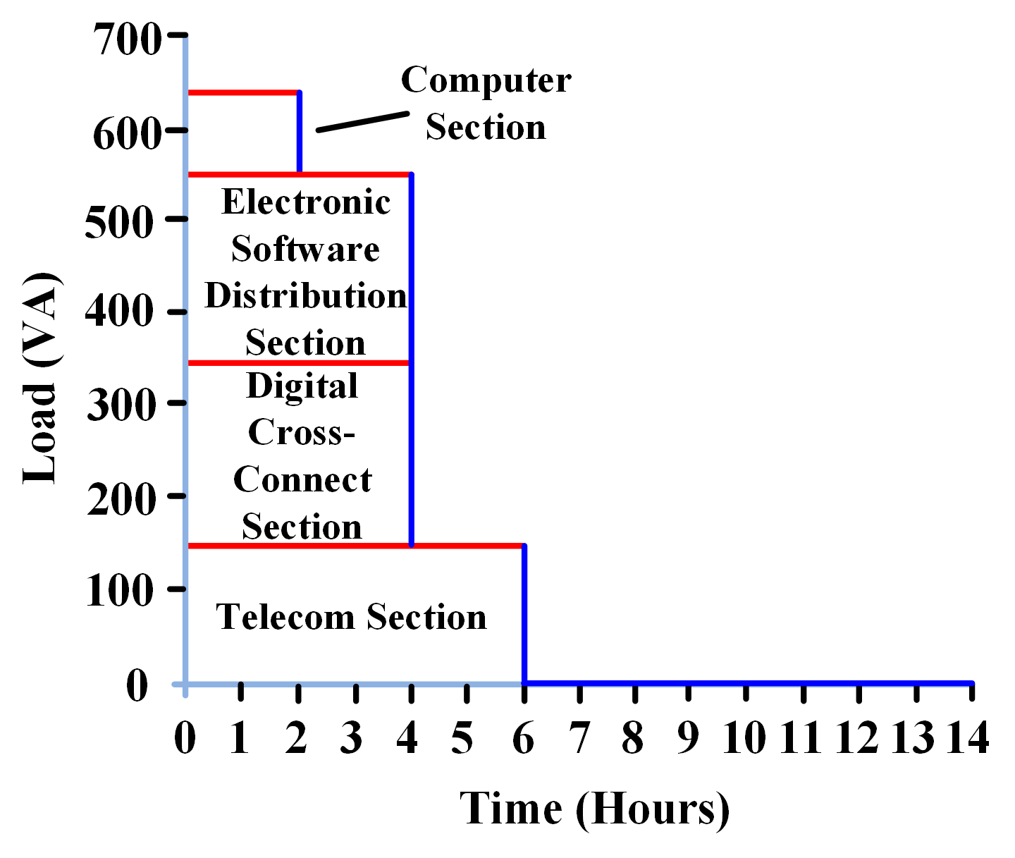
Figure 1: Load Profile
Step 4: Compute the Desired Battery Capacity
In this particular example, we will apply the same battery sizes provided in the Battery Sizing Calculation Example. The total number of cells connected in series is 62 and the battery capacity is 44.42 Ah.
Step 5: Estimation of a Single PV Module Output
A solar PV module for this example possesses the following characteristics:
Peak power of the module, ${{P}_{peak}}=120W$
Temperature coefficient for the peak power, $\gamma=0.35 $ (%/oC)
Manufacturer’s output power tolerance, ${{f}_{manuf}}=4%$
Nominal voltage, ${{V}_{nom}}=12V(dc)$
Let’s assume the average daytime temperature is 25 oC so the effective PV cell temperature can be found using the following equation:
\[{{T}_{effect,cell}}={{T}_{avg,day}}+25=35+25=60{}^{o}C\]
For this particular example, we will use MPPT regulator. De-rating factor for temperature can be computed using the following equation:
\[{{f}_{temp}}=1-\gamma ({{T}_{effect,cell}}-{{T}_{stc}})=1-0.0035\left( 60-25 \right)=0.8775\]
Utilizing a derating factor of 0.98 (for low dirt), the solar PV module de-rated output power can be calculated using the following equation:
\[\begin{align} & {{P}_{\text{module}}}={{P}_{peak}}\times {{f}_{manuf}}\times {{f}_{dirt/soil}}\times {{f}_{temp}} \\ & =120\times 0.96\times 0.98\times 0.8775 \\ & =99.06W \\\end{align}\]
Step 6: Compute the PV Array Size
Considering the following factors:
| Oversupply coefficient ${{f}_{o}}$ | 1.3 |
| Solar PV Sub-system Efficiency ${{\eta }_{ss}}$ | 90% |
For an MPPT regulator, PV modules desired for the PV array can be calculated using the following equation:
$\begin{align} & N=\frac{{{E}_{d}}\times {{f}_{o}}}{{{P}_{\text{module}}}\times F\times {{\eta }_{ss}}} \\ & =\frac{3245\times 1.3}{99.06\times 5.01\times 0.90}=\text{9}\text{.44 Modules} \\\end{align}$
So, for this particular solar PV array, total 10 modules are required.
Solar PV System Sizing Key Takeaways
Understanding the precise methodology for sizing standalone solar PV systems is critical, especially for applications in remote or off-grid areas where traditional power infrastructure is not feasible. Each step—from estimating solar irradiation and profiling electrical loads to calculating battery storage and configuring the PV array—ensures that the system is not only reliable but also efficient and cost-effective. These calculations, grounded in Australian standards and focused on crystalline silicon technology, form the foundation for designing systems that can withstand real-world uncertainties like temperature fluctuations and seasonal solar variability. Moreover, the principles outlined can extend to hybrid energy systems, enhancing their performance in commercial, residential, and industrial settings.