Inductive Reactance
Alternating current flow in an inductor depends on the applied voltage and on the inductive reactance of the inductor. The inductive reactance is proportional to the inductance value and the frequency of the alternating supply voltage.
When an alternating voltage is applied to a pure inductance, the current that flows through the inductance lags its terminal voltage by 90o.
When a changing current flows through an inductor, a self-induced voltage is developed. Its polarity is such that it opposes the change. The emf varies directly with the rate of change of current. This opposition is called inductive reactance. And it is a property of all inductors. Inductive reactance is measured in ohms and is represented by XL, where X indicates reactance and the subscript L implies that it is inductive. If the current change is sinusoidal, the inductive reactance can be calculated from the following equation:
${{X}_{L}}=2\pi fL\text{ }\cdots \text{ (1)}$
Where
2π=one cycle in radian measure
F=frequency in Hertz
L=inductance in Henry
Because angular velocity, 2πf, is frequently written as ω, we can write equation 1 as follows:
${{X}_{L}}=\omega L\text{ }\cdots \text{ (2)}$
And analysis of equation 1 indicates that inductive reactance is directly proportional to frequency and inductance. The following example explores this relationship:
Example
Calculate the inductive reactance of an 8 H filter choke at 60 Hz and at 120 Hz?
Solution
At 60 Hz:
${{X}_{L}}=2\pi fL=6.28*60*8\cong 3016\Omega $
At 120 Hz:
${{X}_{L}}=2\pi fL=6.28*120*8\cong 6032\Omega $
This example illustrates that if the frequency is doubled, the reactance is doubled the same way.
If the reactance of a particular inductance is known at a given frequency, its inductance can be determined by rearranging equation 1 as follows:
$L=\frac{{{X}_{L}}}{2\pi }$
Example
A small inductor used in a TV receiver has a reactance of 5kΩ at 45 M Hz. What is its inductance?
Solution
$L=\frac{{{X}_{L}}}{2\pi }=\frac{5*{{10}^{3}}}{6.28*45*{{10}^{6}}}=1.769*{{10}^{-5}}=17.69\mu H$
Graph of XL
Equation 1 is linear because XL varies directly as the product of the linear terms f and L. if we plot inductive reactance against frequency, we will have a graph like the one shown by the solid line in figure 1, which happens to be for 8 H filter choke of example 1. If the frequency were increased beyond 120 Hz, the reactance line would increase beyond the limits shown.
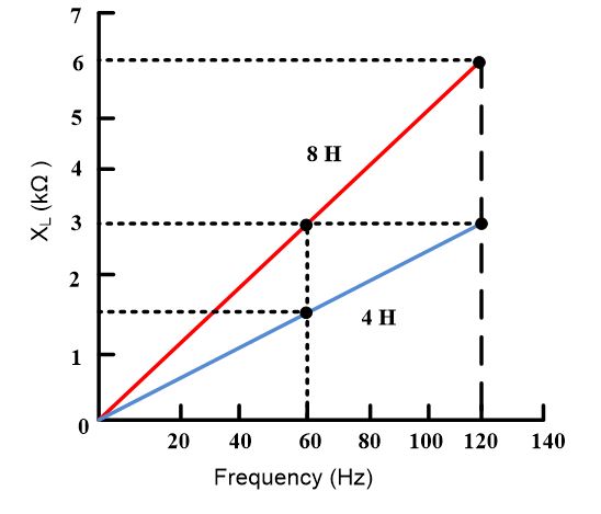
Fig.1: Graph of XL versus frequency for an 8 H and a 4 H inductor
- You May Also Read: Capacitive Reactance
Suppose the inductance used in Example 1 was changed to 4 H. how would the reactance vary with frequency? Since there is a direct relation between inductive reactance and frequency, we can expect XL to be reduced to one-half of its’s value at 60 Hz and 120 Hz. Plotting the reactance of the 4 H inductor on the graph of figure 1 results in the dotted line indicated. Observe that the slope (steepness) is one-half that of the 8 H inductance line. If the value of L were increased to 16 H, we would expect the slope line of its line to be twice that of the 8 H line.
XL in series and in parallel
Inductive reactance’s in series or in parallel are treated in the same manner as resistances, as shown in figure 2.
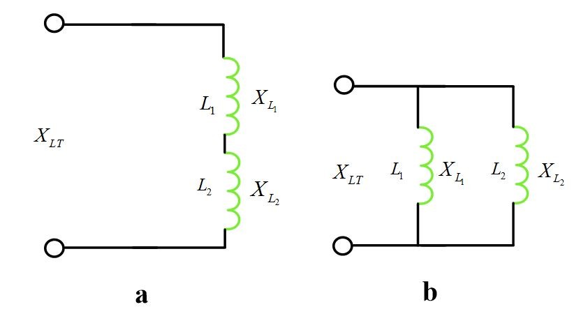
Fig.2: Reactances: (a) In Series (b) In Parallel
Hence, the total inductive reactance of two or more series-connected inductors is as follows:
${{X}_{LT}}={{X}_{{{L}_{I}}}}+{{X}_{{{L}_{2}}}}+\cdots +{{X}_{{{L}_{n}}}}$
For two parallel-connected inductive reactance’s, the formula is as follows:
${{X}_{LT}}=\frac{{{X}_{{{L}_{I}}}}{{X}_{{{L}_{2}}}}}{{{X}_{{{L}_{I}}}}+{{X}_{{{L}_{2}}}}}$
When three or more inductive reactances are in parallel, the reciprocal formula is used:
$\frac{1}{{{X}_{LT}}}=\frac{1}{{{X}_{{{L}_{1}}}}}+\frac{1}{{{X}_{{{L}_{2}}}}}+\frac{1}{{{X}_{{{L}_{3}}}}}+\cdots +\frac{1}{{{X}_{{{L}_{n}}}}}$
Voltage drops and current flows are calculated by using Ohm’s law, except that XL is substituted for R.
Inductive Susceptnce
The reciprocal of resistance R is conductance G, which is the measure of a resistive circuit’s ability to pass the current. Similarly, inductive reactance XL has its reciprocal in inductive susceptance, for which the symbol is BL.
Inductive susceptance is a measure of a purely inductive circuit’s ability to pass current, and like conductance, its unit is the Siemens, S.
The inductive susceptance formula can be expressed as:
${{B}_{L}}=\frac{1}{{{X}_{L}}}$
Inductive Reactance in AC Circuit Key Takeaways
In conclusion, understanding inductive reactance in AC circuit is crucial for designing and analyzing electrical systems. The relationship between inductance, frequency, and reactance helps engineers and technicians optimize circuit behavior and ensure efficient energy transfer. By analyzing how inductive reactance behaves in series and parallel circuits, it becomes possible to design circuits that meet specific voltage and current requirements. Additionally, the concept of inductive susceptance, as the reciprocal of inductive reactance, provides further insight into a circuit’s ability to pass current.