The article explains the concept of inductance and the behavior of inductors in electrical circuits, focusing on how they function in series and parallel combinations. It also covers the calculation of inductance and the formula for the energy stored in an inductor.
When a conductor has current through it, it becomes surrounded by an electromagnetic field. This field leads to a property known as inductance (L), which opposes any change in the current. Inductors are components that are designed to have this property. In this module, we will discuss the basic construction of inductors, how they may be combined in Series and Parallel fashion, and the way that they behave in circuits.
An inductor is an electrical component, formed by a coil of wire, which exhibits the property of inductance. The amount of inductance a coil exhibit is measured in henries (H).
A Henry is defined as a rate of change in current of one ampere per second inducing one volt across the coil.
However, the Henry is a rather large unit and inductance is most often measured in millihenries (mH) or microhenries (µH).
Inductor Basic Structure
Figure 1 shows a basic inductor with the magnetic lines of force and current direction. The amount of current flowing through the coil is proportional to a size of the field; therefore, a changing current will cause a changing magnetic field around the inductor. This changing field is what causes the induced voltage across the coil. This voltage is in the opposite direction from the current and is what opposes the change in current.
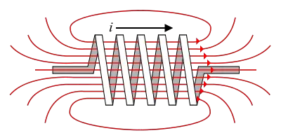
Figure 1 – Basic Inductor
The inductance of a coil is greatly affected by the material that the wire is wrapped around. The inner material, known as the core, can either be non-magnetic (air, wood, etc.) or magnetic (iron, steel, etc.). The permeability of the core is a measure of its resistance to magnetic lines of force. Since the lines of force control to the amount of inductance, the permeability of the core (µ) is directly related to the inductance.
Other characteristics of the inductor that control the amount of inductance are the cross-sectional area of the core (A), the number of turns in the coil (N), and the length of the coil (l). The inductance is found using the following formula:
\[L=\frac{{{N}^{2}}\times \mu \times A}{l}\]
Two other characteristics of inductors are winding resistance and winding capacitance. The winding resistance is the measure of the DC resistance of the wire making up the coil. The winding capacitance is a side effect caused by the multiple turns of wire being in close proximity. These can affect a circuit if the inductor is extremely large or the frequency is extremely high; however, in most circuits, these can be ignored in calculations.
Determine the inductance of the coil given the following values:
N = 350, µ = 0.25 × 10⁻³ H/m, l = 1.5 cm, diameter of core = 0.5 cm
First, find the area of the core; then, substitute the given values into the equation for inductance to find the answer:
$A=\pi {{r}^{2}}=\pi \times {{0.005}^{2}}=1.96\times {{10}^{-5}}{{m}^{2}}$
$L=\frac{{{N}^{2}}\times \mu \times A}{l}=\frac{{{\left( 350 \right)}^{2}}\left( 0.25\times {{10}^{-3}} \right)\left( 1.96\times {{10}^{-5}} \right)}{\left( 0.015 \right)}=40mH$
Inductors in Series
The picture in your head several inductors connected end to end. If you move them closer and closer together, they would eventually look like on large coil of wire. This is the way a series inductive circuit works. Multiple inductors in series simply add up to form a larger inductor. The formula for finding the total inductance in series looks similar to the total resistance in series.
The method for determining the total inductance of the following circuit is similar to that used for series resistors. According to Kirchhoff’s voltage law, we can write following equation for the following figure:
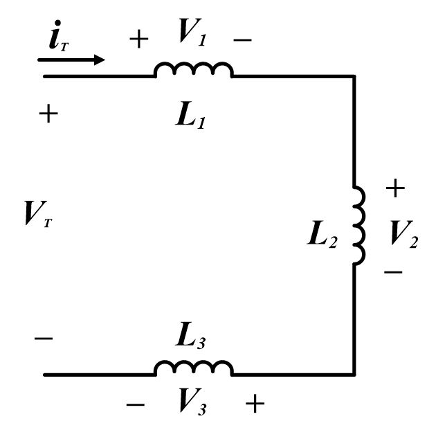
${{V}_{T}}={{V}_{1}}+{{V}_{2}}+{{V}_{3}}\text{ }\cdots \text{ (a)}$
The current flowing in the circuit is iT. The rate of change of current flowing in the circuit is $\frac{d{{i}_{t}}}{dt}$.
Dividing both sides of equation (a) by $\frac{d{{i}_{t}}}{dt}$, we obtain following expression:
\[\frac{{{V}_{T}}}{{}^{d{{i}_{t}}}/{}_{dt}}=\frac{{{V}_{1}}}{{}^{d{{i}_{t}}}/{}_{dt}}+~\frac{{{V}_{2}}}{{}^{d{{i}_{t}}}/{}_{dt}}+\frac{{{V}_{3}}}{{}^{d{{i}_{t}}}/{}_{dt}}\text{ }\cdots \text{ (b)}\]
The left side of equation (b) is the total voltage divided by the rate of change of current. This term gives the total inductance LT. Each term on the right side of equation (b) gives the value of an individual inductance:
\[\frac{{{V}_{1}}}{{}^{d{{i}_{t}}}/{}_{dt}}={{L}_{1}}\]
\[\frac{{{V}_{2}}}{{}^{d{{i}_{t}}}/{}_{dt}}={{L}_{2}}\]
\[\frac{{{V}_{3}}}{{}^{d{{i}_{t}}}/{}_{dt}}={{L}_{3}}\]
So, the total inductance would be,
${{L}_{T}}={{L}_{1}}+{{L}_{2}}+{{L}_{3}}\text{ }\cdots \text{ (c)}$
Equation (c) states that when inductors are connected in series, the total inductance is the sum of the individual inductances.
If there are two or more equal value inductors in series, the total inductance may be found by;
${{L}_{T}}=NL$
Where N is the number of equal inductors and L is the value of the single inductor.
Inductors in Parallel
Inductors can also be combined in parallel circuits. Connecting inductors in series increased the total inductance; so, it stands to reason, connecting inductors in parallel should decrease the total inductance.
Just as series inductors act like series resistors, parallel inductors act like parallel resistors. The formula for finding total inductance in a parallel circuit looks very similar to the one for total resistance in a parallel circuit.
By Appling Kirchhoff’s current law to the following figure, we can determine how inductors in parallel combine;
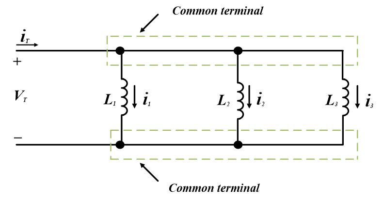
$~{{i}_{T}}={{i}_{1}}+{{i}_{2}}+{{i}_{3}}\text{ }\cdots \text{ (d)}$
In order to express above equation as a rate of change of current take derivative on both sides;
\[\frac{d{{i}_{T}}}{dt}=\frac{d{{i}_{1}}}{dt}+\frac{d{{i}_{2}}}{dt}+\frac{d{{i}_{3}}}{dt}\text{ }\cdots \text{ (e)}\]
Since voltage across an inductor is
${{V}_{L}}=L\frac{di}{dt}$
And also since VT is the total voltage across the parallel inductance,
$\frac{{{V}_{T}}}{{{L}_{T}}}=\frac{{{V}_{T}}}{{{L}_{1}}}+\frac{{{V}_{T}}}{{{L}_{2}}}+\frac{{{V}_{T}}}{{{L}_{3}}}\text{ }\cdots \text{ (f)}$
Dividing both sides of equation (c) by VT would give us following equation;
$\frac{1}{{{L}_{T}}}=\frac{1}{{{L}_{1}}}+\frac{1}{{{L}_{2}}}+\frac{1}{{{L}_{3}}}\text{ }\cdots \text{ (g)}$
Equation (g) states that reciprocal of the total inductance is equal to the sum of reciprocals of the individual inductances connected in parallel.
If two or more parallel inductors are equal. The total inductance may be determined by dividing the value of one of the inductors by the number of equal inductors.
${{L}_{T}}=\frac{L}{N}$
Whereas L is the value of one of the equal indicators and N is the number of equal inductors.
Again, picture several inductors connected together—except, this time, they are in parallel. In a parallel circuit, the current is divided amongst the branches; so, less current is flowing through each inductor. This results in less induced voltage, which results in less total inductance.
Energy stored in an inductor
The power entering in an inductor at any instant is;
$P=Vi=Li\frac{di}{dt}$
When the current is constant, the derivative is zero and no additional energy is stored in the inductor. When the current increases, the current derivative has a positive value and the power is positive. The total energy in the inductor at any given time is the integral of the power from minus infinity to that time;
${{W}_{L}}=\underset{-\infty }{\overset{t}{\mathop \int }}\,Vi~dt=\underset{-\infty }{\overset{t}{\mathop \int }}\,Li\frac{di}{dt}dt$
As we know that
$i\left( -\infty \right)=0$
So,
${{W}_{L}}=\underset{0}{\overset{i}{\mathop \int }}\,Li~di$
After integration, we have final energy expression;
${{W}_{L}}=\frac{1}{2}L{{i}^{2}}\text{ }\cdots \text{ (h)}$
WL= energy stored in the inductor at time t in Joules
i = the current in the inductor at time t in ampere
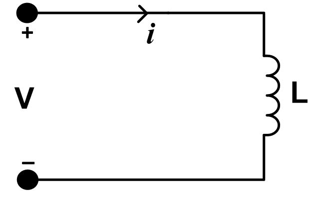
Equation (e) indicates that total energy in the inductor depends only on the instantaneous value of the current. In order for the energy stored in the inductor, as given by equation (e), to be positive, the current and the voltage must have consistent signs, as shown in the following figure:
You May Also Read:
Resistors in Series and Parallel
Capacitors in Series and Parallel
Inductors in Series and Parallel Key Takeaways
Understanding inductance and the behavior of inductors in electrical circuits is crucial for designing efficient and functional electronic systems. The ability to calculate inductance, combine inductors in series and parallel configurations, and determine the energy stored in an inductor allows engineers to manage how current flows and changes in a circuit. These principles are especially important in real-world applications such as power supplies, filters, transformers, and radio-frequency circuits, where inductors are used to store energy, suppress noise, and control signal flow.
3 thoughts on “Inductors in Series and Parallel | Energy Stored in Inductor”