The article explains the fundamental relationship between voltage, current, and resistance using Ohm’s law. It also covers concepts such as electric current, voltage, and resistance, providing practical examples and methods for measuring current using devices like ammeters and multimeters.
Mathematically, it is expressed as:
$V=IR$
Where,
V is measured in Volts
I is measured in Amps
R is measured in Ohms
Electric Current
The electric current is a measure of the rate of flow (i.e., how many per second) of electrons. In fact, electric current is the rate of the electric charge of those electrons, because we are concerned about the electric charge, not the numbers, corresponding to electrons.
If 6.241 ×10¹⁸ electrons move through a wire in 1 sec (i.e., if these many electrons pass a given cross-section of a wire during a 1 sec period), the electric current is 1 amp (1 A).
The amount of electric charge corresponding to this number (6.241 × 10¹⁸) of electrons is called 1 coulomb. Thus, we may say a flow of 1-coulomb electricity in 1 sec is 1 A.
Coulomb: Measure of the amount of electricity equal to the electric charge of 6.241 × 10¹⁸ number of electrons.
For these many electrons to move, it is not necessary that their speed be high. It is the volume that counts more because it is the amount of electric charge that is important.
The speed of electrons does not play any role in electrical current, although electricity travels fast, close to the speed of light. The reason for electricity to move very fast is the simultaneous transfer of electric charge along with a conductor.
In fact, from a mechanics view, electrons cannot go very fast, because although very tiny, they still have mass and follow the rules of motion.
Yet you may not get a tangible feeling for how much 1 A of current is. This will gradually become clearer for you as we continue this discussion.
Consider a lightbulb at home; on these, “110 V, 100 W” is written. See how bright (and hot) the filament is when it is connected to electricity. One amp current is around the electric flow rate giving that much heat and intensity to that lightbulb.
The fuse box at many homes in North America has a capacity of 100 A. That means it is possible to have a maximum current of 100 A at home. Each regular switch at home is capable of carrying 15 A. From these numbers you can imagine what can happen if you touch the wires.
Electric Voltage
Voltage is the electric potential that causes electrons to move around a closed circuit. Volt is the unit of measure for voltage.
Volt is defined as the value of the potential difference for which the energy of one coulomb of electric charge (i.e., the charge of 6.241 × 10¹⁸ electrons) is one joule. Joule is a unit for measuring energy. This official definition of volt may not be much help to understand how much 1 V is.
A better understating is possible by considering that each small dry battery you use in your battery-operated devices is 1.5 V, the car battery is 12 V, and the electricity at home is around 115 V. Also, lightning during a thunderstorm has millions of volts.
You can touch the two sides of a small battery (1.5 V) without any fear, while you might be cautious about doing the same for a car battery.
You should not touch the wires (if bare) at home because if the voltage there does not kill, it definitely causes injuries and gives a disturbing shock.
Similarly, higher voltages are more dangerous; lightning is a high-intensity voltage that if directly hits someone, there is no hope for survival.
Ohm’s Law: Relationship between Voltage, Current, and Load Resistance
Ohm’s law is probably the most fundamental as well as the important relationship that defines the relationship between voltage and current in a circuit. Try to master the meaning of Ohm’s law before continuing any further.
Ohm’s law: One of the most important laws of electric circuits: the relationship between the voltage across a component, the current in the component and the electric resistance exhibited by the component to the flow of electricity. For a simple resistor, it is V = RI.
Ohm’s law states that if the current in a resistor with a resistance R is I, then the voltage across the resistor (the voltage between the two ends of the resistor) is V, such that
$\begin{matrix} V=IR & {} & \left( 1 \right) \\\end{matrix}$
Where R is in ohm, I is in amp, and V is in volt.
This law also implies that if a voltage of V volt is applied to a resistance of R ohm, then the current is I ampere; that is, the current, voltage, and resistance between two points are always related to each other.
Ohm’s Law Example 1
A light bulb filament and the wires connecting it to a 12 V battery altogether have a resistance of 5 Ω. Find the current is in the light bulb filament?
Solution
Substituting for the voltage and the resistance in Equation 1 leads to
$\begin{align} & 12=5\times I \\ & I=12\div 5=2.4A \\\end{align}$
Ohm’s Law Example 2
If the same lightbulb as in Example 1 is connected to a 1.5 V battery, what is the current?
Solution
The resistance of the lightbulb does not change, because it is the physical property of the metallic wires involved. Thus,
$I=1.5\div 5=0.3A$
Note, however, that when a filament is warmed and its temperature has changed, its resistance also changes. Here, for simplicity, we have assumed that the change in temperature is not high enough to affect the resistance.
There are other meanings embedded in Ohm’s law, which we need to pay attention to.
- The relationship between the voltage across a resistor and the current through that resistor is linear. That is, if the voltage doubles, the current doubles, too.
- By the same token, if the resistance of the resistor does not change, then, if the voltage drops in value (decreases), the current also decreases. Similarly, if the voltage increases, the current increases.
- For a constant resistor, if the voltage across it remains unchanged, the current through it remains unchanged. Alternatively, if the current through the resistor does not change, it implies that the voltage across it has not changed.
Note that it is always the voltage applied to a resistor that determines how much the current through the resistor is.
In conjunction with Equation 1 we have the following equations that determine the current in terms of the voltage and resistance and the resistance in terms of the voltage and the current:
\[\begin{align} & \begin{matrix} I=\frac{V}{R} & {} & \left( 2 \right) \\\end{matrix} \\ & \begin{matrix} R=\frac{V}{I} & {} & \left( 3 \right) \\\end{matrix} \\\end{align}\]
It is always the voltage applied to a resistor that determines how much the current through the resistor is.
Ohm’s Law Example 3
A resistive element (has only resistance) has a resistance of 50 Ω and is connected to 120 V. If as a result of the generated heat the resistance of the element increases by 10 percent, what current is in the element?
Solution
Initial current in the element is
$I=120\div 50=2.4A$
After the element is heated its resistance increases by 10 percent and changes to
$\begin{align} & 50\times \frac{110}{100}=55\Omega \\ & I=120\div 55=2.18\Omega \\\end{align}$
Ohm’s Law Example 4
While the resistive element in the previous example is connected to the 120 V, the voltage changes to 130 V; determine the new current in the element.
Solution
Change in the voltage is relatively small, and it does not affect the resistance of the element. Thus, the new current is
$I=130\div 55=2.36A$
Ohm’s Law Example 5
When a light bulb is connected to 120 V supply, it lights up and the current is 0.5 A. If the applied voltage is 220 V instead, what is the current?
Solution
Although for this problem one can numerically find a value for the new current because the voltage is almost doubled, the physical lightbulb cannot withstand the higher current and its filament will blow.
Measuring Electric Current
Any electric circuit has a current in it based on the components in the circuit and based on the voltage of its source. Often, it is necessary to measure the current in a circuit for diagnosing problems and repairs. For measuring current we use an ammeter, a device directly graduated in amps and decimal fractions of an amp.
To measure current in a circuit, an ammeter must be inserted inside the circuit; that is, it must become part of the loop forming the circuit.
Figure 1 shows that for measuring the current in a circuit you need to open the circuit at one (appropriate) point. Then you connect the two leads of the meter to the open ends of the circuit. In this way, the ammeter integrates to the loop and becomes part of the circuit. See Figure 2.
Ammeter: Device to measure electric current.
To measure current in a circuit, an ammeter must be inserted inside the circuit. The circuit must be opened for this purpose. For measuring current one can use an ammeter, which measures the electric current only or uses a multimeter.
A multimeter is a multipurpose device that can measure current in addition to voltage and resistance. It has the capability to measure additional entities, such as capacitance and frequency.
In circuit schematics, a circle with a letter “A” in it represents an ammeter, as shown in Figure 1. Similarly, a circle with a letter “V” in it represents a voltmeter, which measures voltage.
Note that all the components (including the source) and wires in a single circuit (one loop only) have the same current.
Multimeter: Device for electrical measurements with selectable switches to function as voltmeter, ohmmeter, and ammeter, and some more capabilities (all in the same unit).
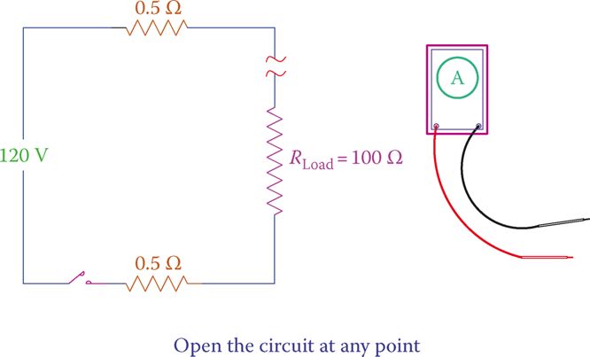
Figure 1 Step 1 for measuring the current in a circuit.
Because in DC electrical current has one direction and in AC electric current direction constantly changes, measuring current in AC and DC is not done by the same ammeter.
For DC a DC meter must be used. In multimeters switching from AC meter to DC and from current to voltage and so on can be done using a selector switch with which one selects the desired choice.
In measuring DC current the red lead of the meter must be connected to the positive side and the black lead to the negative side. If the leads are switched, the reading will be negative. (The needle is forced to turn to the left in an analog device.)
In some ammeters (not multimeters) with a needle, the zero point is in the middle and the motion of the needle indicates both positive and negative readings. This is helpful for the circuits in which current can be either positive or negative.
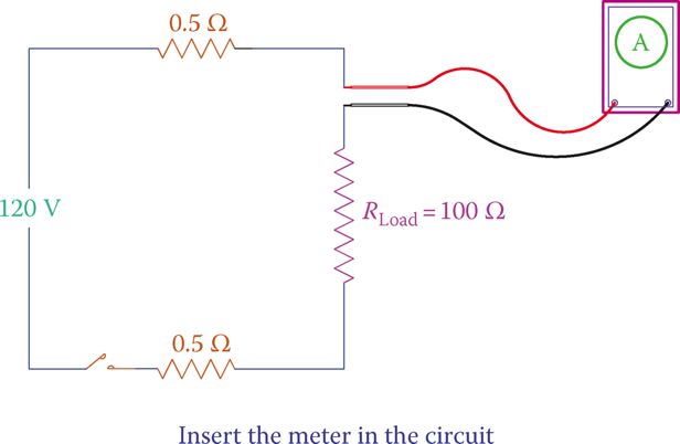
Figure 2 Step 2 for measuring the current in a circuit.
Measuring Electric Voltage
Because the voltage is the potential difference between two points, to measure voltage, the two leads of a voltmeter must be connected to those points. Pay attention for measuring voltage; you should not open the circuit. Whereas for measuring current, one must open the circuit.
In Figure 3 we need to measure the voltage across the load. Thus, the voltmeter is connected at points A and B so that the load is between points A and B (Figure 4). The measured value is the voltage applied to the load. A voltmeter, in fact, measures the voltage difference between two points.
Voltmeter: an Electrical instrument to measure electric voltage.

Figure 3 Use a voltmeter to measure the voltage between two points.
Note that, whereas in a single (one loop) circuit there is only one current, there are various voltages depending on the number of components in the circuit and where the measurement is made.
For instance, in Figure 5 there are a 100 Ω load and two 0.5 Ω wires connecting the load to the 120 V power supply. We may measure the voltage between each pair of points A, B, C, D, and E; for example, A-B, A-D, B-C, B-E, and so on.
The measurement across the source shows the source voltage. Note that in Figure 5 all the points A to E are selected at a graphically suitable point in the line connecting two elements together. Any other point on each line denotes the same point of the circuit.
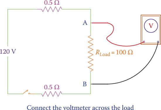
Figure 4 Measurement of the voltage across two points.
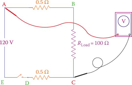
Figure 5 There are numerous voltages between various points in any circuit.
In DC electricity, voltage measurement shows the polarity, too. So, if the positions of the leads of a meter are swapped, in a digital meter the reading will appear with a negative sign, but in an analog meter, the reading cannot be done because the needle is forced to move to the left.
A voltmeter measures the voltage difference between two points by connecting the meter leads to those points.
In any measurement, care must be taken that all the connections are clean and tight. This is especially true for the leads of a handheld meter. Make sure that you firmly hold the leads against the contact points. Otherwise, mistakes in readings are possible. For any measurement, make sure that the measuring leads are firmly held at the contact points.
Voltage Current and Resistance Key Takeaways
Understanding the relationship between voltage, current, and resistance is essential for various real-world applications, from designing electrical circuits to diagnosing and repairing electronic devices. Ohm’s law serves as the foundation for analyzing and optimizing electrical systems, ensuring efficient power distribution in industries, households, and advanced technologies. Measuring current using ammeters and multimeters allows engineers and technicians to maintain safety and functionality in electrical networks. These concepts are vital in fields such as electrical engineering, telecommunications, and power systems, making their practical knowledge indispensable for innovation and problem-solving in modern technology.