The article provides an overview of various computer storage devices, including floppy disk drives, tape drives, hard drives, optical drives, flash drives, and solid-state drives. It outlines their basic functions, evolution, capacities, and key features, emphasizing the technological advancements and usage trends over time.
Storage Devices
Floppy disk drives, tape drives, hard drives, optical drives, flash drives, and solid-state drives comprise the storage options for computers.
Floppy Disk Drives
Floppy disk drives were the primary data transfer medium until the early 21st century. Since 2006, many of these drives have become just an add-on feature. On a rare occasion that one is needed nowadays, the best approach is to buy an external USB floppy disk drive.
Floppy disks evolved historically from huge disk drives that were used in the early days of computing. The 5¼ inch floppy disk has a capacity of 360 KB and the 3½ inch disk has a capacity of 1.44 MB.
The 3½ inch disk, picture in Figure 15 is the most common one found today. Floppy disks are used to store files and programs.
For a few years, computers had both 3½ inch and 5¼ inch floppy disk sizes. By the mid-1990s, the 5¼ inch version had fallen out of popularity, partly because the diskette recording surface was easily contaminated by inadvertent fingertip touching through the open access area of the disk.
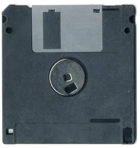
Figure 15: 3½ Inch Floppy Disk
Floppy Drive Cables
Floppy drive controllers are capable of managing two drives depending on the type of floppy drive cable. These drives are always designated as the A: drive and the B: drive. Their position on the cable determines the drive selection. The type of drive is set in the CMOS.
Since the floppy drive cable is not keyed it is important that pin 1 of the cable is plugged into pin 1 on the drive. The colored stripe with lettering in Figure 16 indicates pin 1.
Floppy drive cables have three 34-pin connectors. There is a twist between two of the end connectors. The connector at the end near the twist is for the A: drive. The connector in the middle of the cable is for the B: drive. And the other end plugs into the motherboard.

Figure 16: Floppy Drive Cable
Tape Drives
Although not found on most home computers, the tape drive is still a viable storage medium. It reads and writes digital data onto a magnetic tape. Businesses will typically use this medium for off-line archival storage.
With its low unit cost, long archival stability, and high capacity (5000 GB+), it is a favorite for large system backups. Tape drives usually have SCSI interfaces. Figure 17 shows an IBM 360 tape drive.
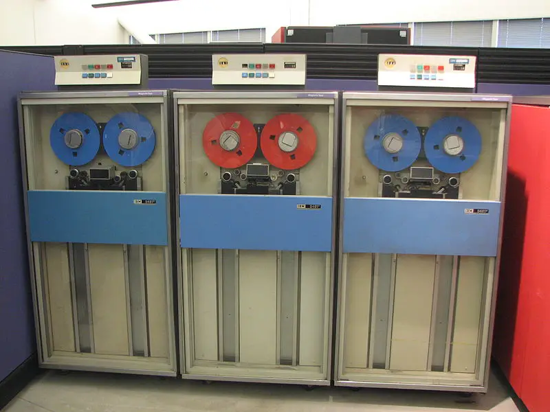
Figure 17: IBM 360 Tape Drive
As prices became more affordable, the use of smaller tape drives became a method of backing up important data in a home environment. However, with the decrease in the price of external USB hard drives and with the growing availability of online backup solutions, tape drives are now rarely used in the home environment. Figure 18 shows a digital data storage tape drive which utilizes digital audio tape.

Figure 18: Digital Tape Drive
Hard Drives
Hard drives are the most common storage medium. Hard drive capacity continues to grow with sizes well over the terabyte range. The faster the drive spins, the faster the reads and writes can be performed.
The 2½ laptop form factor commonly uses 5,400 rpm and 7,200 rpm drives (see Figure 19). 3½ desktop form factors use 10,000 rpm drives. 15,000 rpm drives are common on high-end computers and servers.
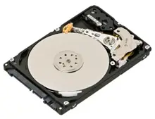
Figure 19: Laptop Hard Drive
Hard Drive Components and Hard Drive Operation
Data is written to a spinning platter in the disk drive by the head of an actuator arm, illustrated in Figure 20.
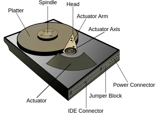
Figure 20: Hard Drive Components
At the factory, a low-level format is performed on a drive to:
- Establish the tracks and sectors on each platter.
- Set the starting and ending points for each sector.
- Prepare the drive to hold blocks of data.
Tracks make a concentric circle around the disk as indicated in red (A) in Figure 21; B indicates a slice-of-a-pie shaped sector; C indicates a wedge-shaped subsector realized as the intersection of a sector and a track; (sub)sectors are often grouped together into clusters, indicated in green (D). Clusters can be read by operating systems, such as Microsoft Windows.

Figure 21: Disk Structure
Multiple platters on a disk drive increase the amount of data that can be stored. Each platter contains two read/write surfaces. There is a (read/write) head hovering over each surface, supported by an actuator arm.
In Figure 22 there are three platters, and so there must be six heads. The arms that support the heads are fixed together so that they always move to the same track. The collection of all the aligned tracks on a stack of platters form a cylinder.
All the heads physically line up on the same track, so they move in and out together. The location of the heads is referred to by a cylinder number.
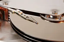
Figure 22: Platters and Heads
A computer user breaks up a drive into one or many parts in a process called partitioning. High-level formatting of each partition then prepares the drive for file storage by setting the cluster size and writing the file structure into the sectors.
Hard Drive Jumper Settings
Most hard drives have four jumper settings to control drive hierarchy:
- Master drive with no slave – for use when there is only one drive on a controller or cable.
- Master drive with slave present – specifies the drive is the master when two drives are connected to the controller or cable
- Slave drive – specifies the drive is the slave when there are two drives connected to the controller or cable.
- Cable select – the cable determines the master and slave. The end device is always the master and the middle device is always the slave. Cable select can cause a slightly longer startup time.
Hard drives come from the factory preset as master with no slave. If two devices with this setting are connected to the same cable, then only one or neither will be found when the computer boots. It is important to check these jumper settings before installing the drive.
Optical Drives
In a few short years, the optical drive has gone from an expensive luxury to an inexpensive necessity, and now to an inexpensive, usually unnecessary, option for modern computers. Optical drives are commonplace in personal computers primarily because of their inexpensive medium, high capacity, and broad application.
Standard optical media is a plastic disk which is 12 cm in diameter and 1.2 mm thick. The base unit of measurement for a compact disk (CD) writer is 150 kbps – so a 40x CD burner runs at 150 × 48 = 7,200 kbps.
Reading an Optical Disk
The fundamental job of a compact disk (CD) player is to focus a laser on the disk and read the bumps. The laser beam passes through the polycarbonate layer of a CD, reflects off the aluminum sublayer, and back to an optoelectric detector. The electronics in the CD player interpret the changes in reflectivity and converts these changes into binary (1s and 0s).
The CD-ROM Medium
A CD-ROM contains one continuous spiral of data, pictured in Figure 23. The data track is approximately .5 microns (µm) wide with a 1.6-micron separation – a micron is a millionth of a meter.
The bumps and valleys that make up the signal are approximately .83 microns long and 125 nanometers (nm) high – a nanometer is a billionth of a meter. This construction makes the spiral track on a CD-ROM extremely long. If the data track could be removed from a CD-ROM and stretched out into a line, it would be almost 3.5 miles (5 km) long!
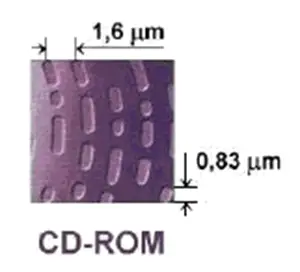
Figure 23: Magnified Spiral of Data on a CD-ROM
DVD Media
DVDs are similar to CDs in their construction. The difference in capacity is the difference in size and width of the data track. The track is 320 nm wide with 740 nm between the tracks, as illustrated in Figure 24. The bumps are 400 nm long and 120 nm high.
A single layer DVD stores 4.7 GB of data, which stretched out in a straight line would be almost 7½ miles long. Double-sided double-layer DVD stores 8.4 GB of data, which stretched out in a straight line would be approximately 30 miles long. A double-sided, double-layer DVD stores 17 GB of data.
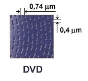
Figure 24: Magnified Spiral of Data on a DVD
Blu-ray Media
Blu-ray disks are exactly the same size as CDs and DVDs, except for the size and spacing of the tracks. The name Blu-ray comes from the blue laser used to read the disk.
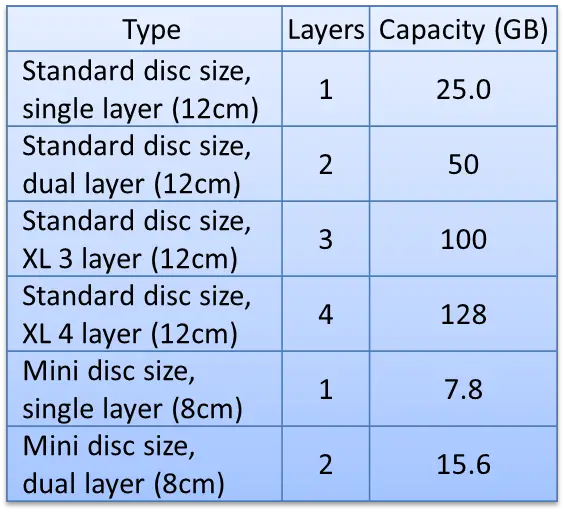
A standard size single layer Blu-ray disk has a capacity of 25 GB, making it the largest optical format available. The major application of Blu-ray disks is as a medium for video material; Blu-ray is the industry standard for storing feature films.
Dual-layer Blu-ray disks store 50 GB of data. Triple layer Blu-ray disks store 100 GB of data. Quadruple layer Blu-ray disks store 128 GB of data. The Blu-ray disk types and their capacities are compiled Table 6.
Table 6: Blu-ray Media
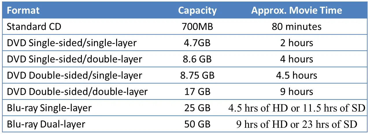
The distinct characteristics of CDs, DVDs, and Blu-ray disks are summarized in Tables 7 and 8. Knowledge of the capacities for optical media is an objective of the CompTIA A+ 220-801 Certification Exam.
Table 7: CD vs. DVD vs. Blu-ray
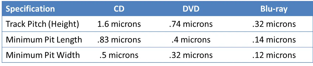
Table 8: CD vs. DVD vs. Blue-ray – Capacities
CD/DVD Audio and Power Connectors
For an IDE PATA optical drive (Integrated Drive Electronics Parallel AT Attachment), an audio cable must be attached to the drive and motherboard to enable audio functionality. SATA drives (Serial AT Attachment) have audio capabilities built-into the cable.
All 5¼ inch drives, such as CD and DVD drives, require a Molex power connector. All 3½ inch drives, such as a floppy disk drive, require a Berg power connector. Both Molex and Berg power connectors operate at 12 V and are keyed so that they can only be inserted one direction.
Flash Drives
Flash drives, also known as thumb drives, include flash memory. Flash memory is a type of non-volatile RAM or NVRAM. NVRAM draws its power directly from the USB connection but retains its contents when power is lost.
Flash drives are very reliable because they have no moving parts. Flash drives allow up to 100,000 write/erase cycles and have a ten-year shelf life.

Figure 25: Flash Drive
Solid-State Drive (SSD)
Solid-state drives (SSD) are rapidly replacing traditional hard disk drives as the hard drive of choice. SSD use the same type of NVRAM as flash drives. Key features of SSD are:
- No moving parts, so less likely to be damaged by physical events
- Silent
- Same interfaces as hard disk drives
- Very low access time and latency, outperforming even 15,000 rpm hard disks
- Storage capacity rapidly increasing
A drawback of SSDs is that they are more expensive than hard disk drives with the same capacity. They are commonly used now in laptop computers.
Data centers require vast amounts of storage, so typically hard disk drives are used in this setting to limit cost. Some drives are sold as hybrid drives, which combine the features of a hard disk drive and a solid-state drive.
Figure 26 illustrates two types of SSDs.


Figure 26: Solid-State Drives
Compact Flash and Secure Digital Devices
Various types of solid-state memory modules are also used in digital cameras, mobile phones, tablets, and other storage devices. These solid-state memory modules have a wide range of storage capacity, and the storage capacity increases rapidly over time. Common form factors are:
- CompactFlash (CF)
- Secure Digital (SD)
- MiniSD
- MicroSD
- xD
CompactFlash is used in digital cameras and other mass storage devices, ranging in capacity from 2 MB to 256 GB. Secure Digital cards are used in digital cameras, mobile phones, GPS navigation devices, and tablet computers, ranging in capacity from 1 MB to 2 TB capacity. xD is a priority format that is slower than the various SD options. SD, miniSD, and microSD cards are illustrated in Figure 27.
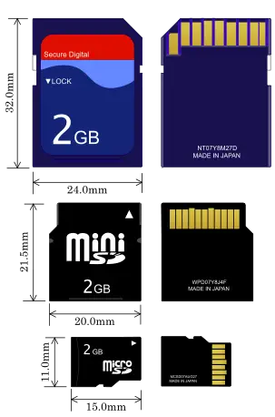
Figure 27: SD Cards
IDE, EIDE, Ultra, and SCSI Controllers
There are several types of interfaces used on storage devices. Each storage device is managed by a controller, and the interface type of a storage device is associated with that of the controller supporting it.
Integrated Device Electronics (IDE) has been used for hard drives, optical drives, and tape drives for many years. The IDE interface is officially known as the AT Attachment. Enhanced IDE (EIDE) is very closely associated with ATA-2, and increases capacity to 8.4 GB. The newer ultra ATA increases the capacity to 50 GB.
Parallel ATA (PATA) devices use the AT Attachment Packet Interface (ATAPI). ATAPI is used with CD-ROM drives and some hard drives. PATA is actually the result of a long evolution from its first incarnation, IDE; ATA-1 was an immediate successor of IDE.
PATA is often equated with the original ATA interface standard. PATA has been superseded by Serial ATA (SATA) as a hard drive interface standard. The PATA standard allows for cable links up to 18 inches, while SATA cables can extend to 3.3 ft.
Another type of interface is Small Computer System Interface (SCSI), which is found on high-end computers and servers. SCSI devices have the controlling electronics on each of the drives. SCSI supports much more advanced interface controllers than EIDE or ATA-2.
PATA, and SATA Cables
PATA cables use a 40 pin keyed connector that attaches to both the drive and the motherboard. The ATA/33 cable has 40 wires, one to each pin, and the ATA/66 has 80 wires, two to each pin. This allows for a greater transfer capacity.
SATA was designed to replace PATA. SATA features include:
- seven pins L-shaped connector
- native hot swapping allows devices to be exchanged without turning the computer off
- one device per controller so no jumper settings are needed
- cable links up to 3.3 ft
- faster transfer speeds
- SATA1 has a transfer speed of 1.5 GB per second
- SATA2 has a transfer speed of 3 GB per second
- SATA3 has a transfer speed of 6 GB per second
Figure 28 displays a SATA cable.
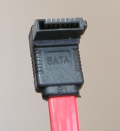
Figure 28: SATA Cable
It is important for a computer technician to know the number of pins, maximum cable lengths, and a maximum number of devices for each type of controller. Data cables connect drives to the controller. Controllers are located on an adapter card or on the motherboard.
Computer Storage Devices Key Takeaways
Understanding the different types of storage devices—from older technologies like floppy disks and tape drives to modern solutions such as flash drives and solid-state drives—is essential due to their significant role in data management and accessibility. These storage devices enable users and organizations to store, back up, and retrieve vast amounts of information efficiently and reliably. As technology continues to advance, newer storage devices like SSDs offer faster performance and greater durability, making them vital for high-speed computing and mobile applications. Overall, the evolution and application of storage devices directly impact productivity, data security, and the overall performance of computing systems in both personal and professional environments.