The article introduces the fundamentals of computer networking, covering the history of networking, components of a networks, and detailed explanations of the OSI model layers. It also includes an overview of data flow through the OSI layers, a reference model, and a review of binary math relevant to networking concepts.
Lesson Objectives
By the end of this lesson, you will be able to:
1. Describe the steps involved in developing an effective troubleshooting methodology.
2. Identify CompTIA and the Learning Domains for the Network + exam.
3. Describe what computer networking is and how it was initiated.
4. Compare the layers of the OSI model.
5. Convert decimal numbers into binary.
Networking History
In the 1960’s DARPA initiated the goal of trying to communicate between multiple computational systems. By networking or interconnecting multiple computational systems, participants were able to share and develop research that would later form the Internet. A computational system processes calculations and processes information. A computer, server, mobile phone or network device has a processor/logic unit that computes information.
Today computer networking enables us to share resources and data that result in higher productivity and efficiency.
Examples of the Benefits of Networking
- Network Topology Development
- Printing (local vs. Network)
- File Sharing (local vs. Network) i.e. SharePoint
- Client/Server benefits (Email, Internet, E-commerce, Instant Message Communication, etc.)
- Voice over Internet Protocol
Network
Here some of the components of a network that can be seen. The firewall, router, switch, hub, bridge, and the connected laptops, PC’s, printer and servers interconnect to form a network.
A bridge is no longer used in modern networks and its function of bridging two disjoint networks together, is now a function of a switch.
To be clear, some organizations will have computers on ‘Network A’ and ‘Network B’. These networks cannot communicate with each other because they are disjointed or separated. In cases such as this one, a bridge or switch can be used to join these networks so they can communicate as if they were one contiguous network.
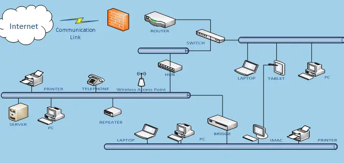
Figure 1 General Representation of a Computer Network
OSI Model
The Open Systems Interconnection (OSI) model was developed by the International Standards Organization (ISO). You can think of the OSI model as a set of building blocks. One block builds upon another. One block needs the other block to perform the task of network communications.
Although it can be an intimidating aspect of study for the CompTIA N+ exam, a high level overview provides a solid foundation to build upon. The Network + exam will focus heavily on OSI Layers 1 – 4. See Figure 2.
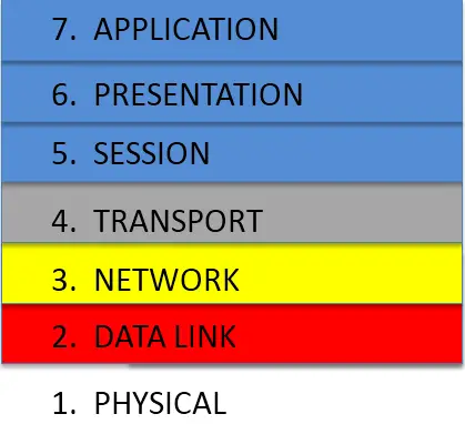
Figure 2 OSI Model Layers 1 – 4: 1) Physical 2) Data Link 3) Network 4) Transport.
Physical: The Physical layer is layer one of the OSI Model. This describes the medium by which network communication can take place. On the CompTIA N+ exam and in the Information Technology field the medium that facilitates data communications is referred to as, media.
Media can be the electrical signals, cables, optical fiber, radio frequency and connectors used when communicating with another system. Some examples of media are phone lines, Ethernet cables, and fiber optics.
Data Link: The Data Link layer is layer two of the OSI Model. This layer passes outgoing data to layer one and receives incoming data from layer one once it has error checked and examined the data packet’s contents.
This layer determines the access method to get the data packets on the wire, fiber optic, or wireless channel and is known as the “media access control layer”. Think of layer one as an electric passenger train with the tracks included. Layer two is like a train stop where a porter (train employee) checks your ticket, tells you whether or not you can board the train, and loads or unloads your baggage when your destination is reached.
Network: The Network layer is layer three of the OSI Model. This layer determines the routing decisions based on the protocol being used and the information in the data packet.
Protocol is a set of rules outlining the format to be used for communication between computational systems.
Think of layer three as your electric train conductor or driver. The conductor looks at your ticket, logical address, and determines how to get you and your luggage to your destination. The conductor or driver is also responsible for identifying or tagging the train line, network segment, and train station, host segment, from which you originated.
Transport: The Transport layer is the fourth layer of the OSI model and is concerned with transmission control. This layer is responsible for ensuring that data moves smoothly between the upper layers session, presentation, and application as well as the lower layers, physical, data link and network.
Outside of the different types of media used to transport data there are also several different protocols which determine how data is processed. The Transport layer is responsible for ensuring these protocols are followed as well.
Think of the Transport layer as the train dispatcher. The dispatcher tells the trains how much luggage (payload) and how many train cars (packet size), are allowed on the tracks (OSI Layers 1-3). When the train and passengers arrives at their destination the dispatcher ensures that their luggage has arrived as well.
Session: The Session layer is layer five of the OSI model. This layer model initiates, manages, and terminates connections between networked devices. When a user connects to another computer system a session is established. Layer five manages this session or connection. Another way to think about this is when you go to a website such as www.collin.edu. When you access a site, a session is established between your computer and the web server that hosts the web page. Sessions are also established between SQL servers, NFS.
Presentation: The Presentation layer is layer six of the OSI. This layer manages and translates data from one code to another if necessary. Translating Code examples include ASCII, JPEG, and HTML. Data Compression and encryption take place at this layer. Encryption devices like Smartcard and Smart card Readers operate at this level of the OSI Model.
Application: The Application layer is the seventh layer of the OSI. This layer can be described as the protocol needed for an Application program to run. An example of this is when you use the Application/program Internet Explorer (IE), it relies on the protocol HTTP or HTTPS to send and receive requests related to displaying web content. Other notable Application layer protocols are: SMTP, FTP, POP3, and IMAP.
When the presentation layer, layer six, receives data, it decompresses, decrypts, or translates the data so the application layer, layer seven can make use of the message or code. This is a two –way process.
The Application layer is responsible for initiating (sending) and receiving a message/request and also interpreting, and servicing the request.
OSI Data Flow
Consider the following example: Requesting a webpage using a browser, Internet Explorer, Firefox or Chrome. This example is based on submitting a request for the webpage ‘www.google.com,’ over HTTP (protocol). Figure 3 illustrates the data flow that occurs between a sending and receiving network device.
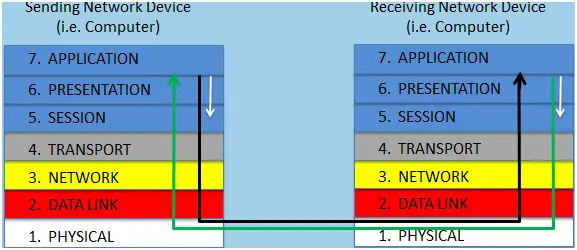
Figure 3 OSI Data Flow
For additional details regarding the process, review the following:
- The data flow begins when a request or data is sent from the browser via the Application layer to the Presentation Layer. If any encryption or compression is needed, that process is handled at the Presentation Layer.
- The Session layer will initiate and maintain the session once it is established with the web server where www.google.com is located. The data is then passed through to the Transport Layer which segments and helps maintain proper format of the data packet. The data then passes through to the Network Layer which records the sending device address and checks the destination address to determine how to get the data packet to the receiving network device.
- The Data Link Layer is responsible for checking the data packet and gathering all necessary elements involved with placing the data on to the Physical Layer. Once the data packet is placed on the media it travels through the internet until it reaches the Physical Layer of the receiving network device.
- The Physical Layer either Copper wire, Fiber optic, or wireless (RF) on the receiving network device receives the data packet. Passes the data packet to the Data Link Layer where the data packet is checked for validity. If the data packet passes the error check, it is passed through to the Network Layer where the data packet is inspected to see if it belongs on the network. Assuming it is in this case, the data packet is routed to the web server host location.
- The Transport Layer ensures the data packets arrive in the proper order and size. The Session Layer maintains the session or connection with the sending network device. The Presentation Layer then decrypts or decompresses the data, if needed, and passes the request for the webpage ‘www.google.com’ over HTTP to the Application Layer. The Application layer services the request for the web page. Lastly, the web server then sends the data back to the sending device where I (the sending machine) can see ‘www.google.com’ on my browser.
OSI Data Reference Model
This reference model (Figure 4) describes another way the OSI model can be conceptualized. Please be sure to refer to previous the information in this lesson regarding the OSI model layers if needed to recall how the OSI layers operate for testing purposes.

Figure 4 Reference Model
The OSI Model does not describe the actual representation of network communication. It is more of a conceptual, logical or theoretical description of how data flows through a networks.
The OSI model is an important concept to understand for the Network + exam. The OSI Model can be used to troubleshoot networks issues and verify functionality at each level. There are other details in the OSI Model that will be revisited; however this should serve as a preliminary introduction.
Math Review: Binary
It is important to know how computers and networks talk to each other. They communicate through a series of 0’s and 1’s (Binary). Binary means that you can represent a numerical value (i.e. 100) using two objects/symbols. Binary means that you can represent a numerical value (i.e. 100) using two objects/symbols.
The understanding of Exponents (xx) is important to calculate binary representations. For instance when you are typing, the computer gets the message that the “T” key has been pressed. The letter T has an ASCII value of 116. In Binary, the letter “T” has the value of 01110100. ASCII value is an aspect of the Presentation Layer.
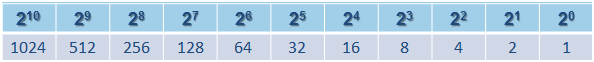
Figure 5 Base 2 Table
If the number “1” is in any of the above place holders you count that number. If the number in any of the place holders is “0” you do not count it. Look at the letter “T” again to see how it is represented in Binary – 01110100. This string (series of numbers) takes up eight place holders. However you only count four. So counting only the place holders in Figure 6 where you have a one (1); you have 64 + 32 + 16 + 4 = 116.
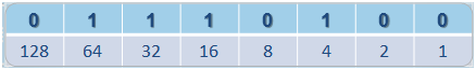
Figure 6 Counting Place Holders
An address is used by computers (IP) and humans (postal mail/email) to send information and data to each other. Computers use two types of addresses, IP and MAC (not Apple related) addresses. However, the IP address is the only one typically represented in Binary.
An IP address is split into four octets, or a group of eight. In other words there are four sections in which 8 bits are available. Those eight bits can have either a one (1) or a zero (0). Using base 2 table for reference IP Address – 10.134.67.5 is represented in Binary as: 00001010.10000110.01000011.00000101 = 10.134.67.5
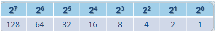
Figure 7 Base 2 Table
Networks Key Takeaways
Understanding the fundamentals of computer networking—including the history, core components, and the detailed OSI model layers—is crucial for effectively designing, managing, and troubleshooting modern networks. These concepts enable seamless communication between devices, support vital applications such as email, web browsing, file sharing, and VoIP, and ensure data integrity and security through well-defined protocols and processes. Knowledge of binary math and addressing schemes underpins how devices uniquely identify and communicate with each other, which is essential for routing and delivering data accurately.