This article introduces computer networking. The types of networks and the types of network topologies are described. The role of a network administrator is explained. Network operating systems are described.
Computer Networks
A computer network is a collection of devices, including computers, connected together for the purpose of sharing data or resources. Several workstations, a printer, and a server linked together is an example of a network, as illustrated in Figure 1.
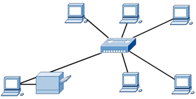
Figure 1: A Network
Networks Empower Computer Users
It really comes down to a simple concept: interconnecting PCs to form a network is extremely convenient because, instead of physically walking between PCs to move data, networks move the data between PCs via media such as over wires or airwaves, at a speed of about half the speed of light, or 93,000 miles per second (try to imagine that). Networking empowers computer users to:
- Share printers
- Share Internet connection
- Share files, data, pictures, and music
- Share resources
- Avoid duplication
- Play multiuser games
- Manage resources
Network Administration
A network administrator is charged with leading the effort to maintain, troubleshoot, and grow the network in line with the needs of the organization it serves.
The role of a network administrator changes in sync with the emergence of transformative networking technologies. A network must be able to adapt in sync with the addition of new devices, personnel, and applications.
The task of maintaining and adapting the network to changing conditions is the work of network administrators. Network administrator responsibilities include setting up new user accounts and services, monitoring network performance, and repairing network failures; in each of these cases, depending on the size of the organization, these responsibilities may actually be assumed by people managed by the network administrator.
Network administrators evaluate new technologies and the associated implementation requirements. Network administrators must measure the benefits of the new technologies against the issues, costs, and problems that they may introduce to the network.
Overview of Networks
Networked computers take on different roles and functions, depending on the communications requirements.
Two computers communicate with each other by using one or more protocols; for example, Server Message Block (SMB) is a protocol used for file sharing between PCs running Microsoft Windows operating systems. The requester takes the role of the client and the responder takes the role of the server. But these roles may switch from computer to computer as needed; again, it helps to think of file sharing as an example. Since no one computer is in control and they are all free to request or respond this is known as peer-to-peer networking. Windows computers are configured to be part of a workgroup to facilitate this type of networking.
Sometimes a computer is set up to take a more dominant role in the network. A computer may manage resources, share files, manage security applications, host backups, and provide services to all the other computers on the network. This is known as client-server networking. Windows computers are configured to be part of a domain to facilitate this type of networking.
By using local area network (LAN) and wide area network (WAN) technologies, computers interconnect to provide services to their users.
Peer-to-Peer Network
Peer-to-peer networks consist of computers behaving as equal partners, acting requesters or responders as the need arises. Figure 2 illustrates a peer-to-peer network.
Each individual user controls its own resources, controlling what they share, which devices to share with, and what passwords to require. Peer-to-peer networks work best with a limited number of computers: 10 or less is ideal.
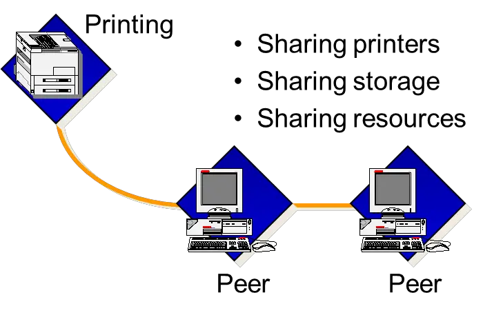
Figure 2: A Peer-to-Peer Network
Client-Server Network
In a client-server network, networked services are located on a dedicated computer, called a server, whose primary function is to respond to the requests of clients. See Figure 3. These services may include access to files, printing, applications, security, and many other services.
Multiple computers can run a single installed application as long the purchased license is for the maximum number of users or computers that access the application at one time.
Typically, desktop computers function as clients and one or more computers with additional processing power, memory, and specialized software function as servers. This arrangement works well in even the largest businesses. This gives the network administrator a centralized location to manage the network.
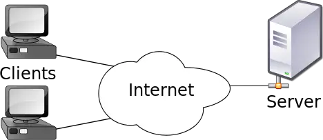
Figure 3: A Client-Server Network
Operating Systems and Network Communication
When using network applications on a modern network, such as web browsing with Hypertext Transfer Protocol Secure (HTTPS), it does not matter what operating system is in use, because network communication is handled by standards-based protocols. The collection of protocols primarily used for modern network applications is called the TCP/IP protocol suite.
All operating systems support the TCP/IP protocol suite. Figure 4 illustrates a network with computers running several distinct operating systems.
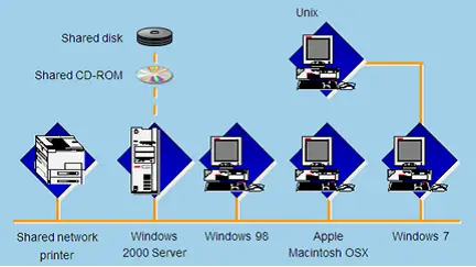
Figure 4: Computers with Different Operating Systems Can Communicate over the Network
Local-Area Networks
The media is the type of cabling technology that connects two devices. Some examples of media include copper cabling, fiber optic cabling, and air (for wireless communication).
A LAN connects computers in a small geographic area such as within a home, within an office, within a building, or within a campus. In its simplest form, a LAN is a small number of computers connected together with common media, as illustrated in Figure 5.
More practically, nowadays a LAN is composed of end user devices connecting to switches, and in turn the switches interconnecting to create a hierarchical network. Every computer and device on the LAN is part of the same network.
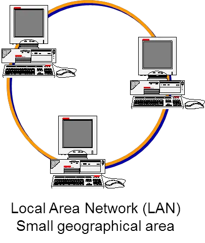
Figure 5: Local Area Network: Small Geographical Area
Wide-Area Networks
A wide area network (WAN) is defined as devices connected together over a large geographic area.
Historically, WANs operate at lower speeds than LANs; but modern WAN links often support greater throughput than the links in the LANs interconnected by the WAN. Historically, WANs used point-to-point serial connections; but modern WANs often utilize high-speed Ethernet links. Point-to-point means that only two devices connect, one on each end of the link.
A home router connects to an ISP and an ISP connects to another ISP, and so on to the final destination – these connections are generally point-to-point links. As a rule of thumb, if some type of modem is in use, then a WAN is part of the picture. Figure 6 illustrates an intercontinental WAN.
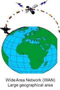
Figure 6: Wide Area Network: Large Geographical Area
Other Types of Networks
Other types of networks include:
- Metropolitan area networks (MANs) are networks that interconnect users with computer resources in an area defined by an urban geography. Think of this as interconnecting campuses of the school district or connecting a branch office to another branch office.
- Personal area network (PANs) are centered around one individual. The most common form of PAN is that created by using a Bluetooth headset with a mobile phone.
- Storage area networks (SANs) are networks dedicated to providing data storage services. All users can access the same storage.
Network-Attached Storage
Network-attached storage (NAS) is a device dedicated to providing data storage services over a network. Although NAS is not a type of network, since a SAN combines networking with storage it seems appropriate to introduce the concept of NAS here.
With NAS, each user has a dedicated storage area that only they can access. A NAS provides both storage and a file system, unlike a SAN, which only provides storage.
Circuit-switched vs. Packet-switched
Packets can enter and exit a network in one of two ways: circuit-switched or packet-switched.
A circuit-switched network connection is one in which all data packets traverse that connection. A traditional landline telephone call involves picking up a receiver, dialing a number, and a telephone circuit connecting the source (phone of the caller) to the destination (phone of the called party). That telephone circuit is maintained for the duration of the call and is terminated when one party hangs up.
A circuit-switched data network behaves roughly the same way. A dial-up connection is a simple example of a circuit-switched network. Circuit-switched networks only exist for the duration of a communication session.
In a packet-switched network connection, each individual packet can take a different path to the destination. Data is sent to the next hop device and that device decides where and how the packet will be forwarded. Packet-switched networks are always on. A broadband cable data connection, a DSL connection, and a T1 connection are examples of packet-switched connections. The Internet itself is a packet-switched network.
Data Transmission
The data channel or wire over which a signal propagates can operate in one of three ways:
- A simplex channel is a single one-way baseband transmission. Examples include radio, television, and clock synchronization on a computer.
- A half-duplex channel allows traffic to travel in both directions but only one direction at a time. A device connected to a half-duplex channel can either transmit or receive. Examples include walkie-talkies and the primary implementation of Ethernet in the 1980s, 10BASE2 Ethernet, where the physical topology is a bus created by thin coaxial cable.
- A full-duplex channel allows traffic to travel in both directions at the same time. 100BaseTX or 1000BaseT connections to Ethernet switches operate in full-duplex mode. Most of the connections made today are a full duplex but can be manually changed to half duplex to accommodate older technologies.
Network Topologies
The term topology, in the context of networking, refers to the general shape of a network. The same network will have both a logical topology and a physical topology.
The logical topology describes the shape of a network in terms of the paths defined by traffic flows and depends on the equipment, the media, and the protocols in use.
The physical topology is literal, showing the exact location of the wires and devices.
A network can have distinct physical and logical topologies. For example, a wireless network may be physically manifested in a star shape, with all devices connecting to a central access point, but is logically manifested as a bus topology because all devices are sharing the same wireless media.
Physical Topologies
A physical topology defines the specific path data will take through the network. The video, Network Topologies – CompTIA A+ 220-801: 2.8 (3:57), discusses the advantages and disadvantages of common network topologies.
The physical topology defines device locations, cabling, and the routes to move data. Networks can have several different physical topologies:
- Bus topology – all devices share the same media. The buses on a motherboard all share the same data channels and therefore comprise a bus topology. Carrier sense multiple access with collision detection (CSMA/CD), the media access method for IEEE 802.3 Ethernet, applies to a bus topology. The drawback is that multiple devices can send data at the same time, causing collisions on the network which greatly degrades performance.
- Ring topology – interconnects devices one to another, forming a ring. The devices communicate by requesting a token, which allows them to send data. Only one host can send data at any given time, eliminating the possibility of collisions. The drawback is if one device fails the entire ring fails.
- Star topology – interconnects devices via a central device. In modern networks, this central device is usually a switch. Each device communicates with the central device, eliminating the possibility of collisions. Only if the central device fails does the network completely fail. A star topology is the one typically used in home networks.
- Extended star topology – essentially the same as the star topology, but with more concentration points. One can make a comparison to a business with multiple branch offices. All the devices in a branch office connected to a switch and then that switch connects back to the main office. This way one branch office may shut down without affecting any of the others. If the main office shuts down, branch offices can still communicate with each other. This model is the most common in schools and businesses today.
- Mesh topology – every device is directly connected to every other device in the network. This topology is very expensive to implement but is very redundant and eliminates a single point of failure. This topology is used by the United States military to connect bases together.
- Cellular topology – wireless concentration points are set up with overlapping signals. As a person moves with his/her device away from one connection point, another connection point picks up the signal so that a connection is never lost.
The physical topology defines the way devices are connected. See Figure 7 to compare the various physical topologies used in networks. Top left to right: Bus Topology, Ring Topology, and Star Topology. Bottom image left to right: Extended Star Topology, and Mesh Topology.
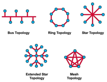
Figure 7: Physical Network Topologies
Logical Topologies
A logical topology is how network devices appear connected to the user. It is the way that the signals act on the network media—the way that data passes from one network device to another without regard to the physical connections of the devices. The two most common logical topologies are:
- Bus: a node broadcasts the data to the entire network. All other nodes then check if the data is intended for them.
- Ring: only one node transfers the data in a network at any given time. The node that possesses the token can transmit the data.
Network Topologies Key Takeaways
- In this lesson, the origins of networking were discussed and computer networks were defined. The role of a network administrator was described.
- Peer-to-peer and client-server networks were defined. LANs and WANs were defined and contrasted. MANs, PANs, SANs, and NAS were introduced.
- Circuit-switched and packet-switched were defined and differentiated. Simplex, half-duplex, and full-duplex channels for data transmission were described.
- Physical and logical network topologies were defined, and the types of network topologies were listed.