In this article, Network devices are categorized in terms of their role in the OSI model, including hubs, (layer 2) switches, routers, and firewalls.
Network devices must be properly configured in order to communicate with other networking devices. For example, the annoying sound heard at the beginning of a fax transmission means that the two fax machines are agreeing on parameters for the transmission.
Serial ports on PCs are used to connect to routers, switches, and firewalls for the purposes of configuring the network devices, typically using a command-line interface. The standard serial communication parameters are:
- 9600-bit rate
- eight data bits
- no parity
- one-stop bit
- no flow control
Figure 1 illustrates a Windows dialog box for setting the serial communication parameters.
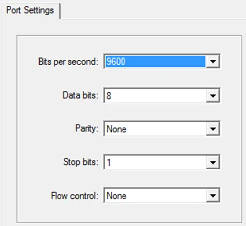
Figure 1. Serial Port Settings
Network Devices Examples
Layer 1 Network Devices
Layer 1 network devices are dumb devices, meaning they make no intelligent decisions about handling data. Most layer 1 devices are one of the following:
- A repeater is a two-port device used to extend an Ethernet connection to allow devices to communicate at greater distances. A repeater strengthens and retransmits signals.
- A hub is a multiport repeater. It may be active (amplifying the signal) or passive (no amplification). Hubs transmit data to all ports regardless of the final destination.
- A modem works in all seven layers but primarily at OSI layer 1. A modem modulates and demodulates signals sent over telephone lines. A modem converts a computer’s digital signal into a land line’s analog signal.
- A transceiver is a device that converts from one medium to another. For example, there are transceivers which convert between twisted-pair and fiber optic media.
Note: Layer 1 devices provide no security options.
Network Interface Card (NIC) – Layer 2 Network Device
Layer 2 devices have some intelligence, in that frame forwarding decisions are made based on MAC addressing. On a computer system, a network interface card (NIC) is a plugged-in peripheral or a built-in component on the motherboard containing one or more ports that support either fiber-optic or twisted-pair connections to the LAN.
While a NIC operates at all seven layers, it primarily functions at layer 2. There are several important considerations to bear in mind when selecting a NIC to use on a network:
- Type of network – Ethernet, Token Ring, or FDDI
- Type of media – twisted-pair, coaxial, fiber-optic, or wireless
- Type of bus – PCI or ISA
USB has become a popular means of connecting to a LAN, either with a USB wireless adapter or with a USB-to-Ethernet adapter. A PCI NIC is pictured in Figure 2.

Figure 2. PCI NIC – a Network Device
Bridges and Switches – Layer 2 Network Device
A bridge is a layer 2 device because forwarding of frames is based entirely on the content of the frame headers. A bridge has two ports that often are associated with distinct media types (e.g., wireless and twisted-pair).
When a bridge receives a frame, it examines the MAC address to determine if the data will be forwarded; if the determination is made to forward the frame, then it cleans and amplifies the signals associated with the frame and transmits the frame.
Historically bridges were used to connect disparate network segments as well as to subdivide collision domains.
A (layer 2) switch is effectively a multiport bridge – it helps to understand the role of switches to thinking of them in this way – see Figure 3. But to be accurate, modern layer 2 switches feature a wide array of technologies, such as virtual LANs (VLANs) that did not exist when switches were first manufactured in 1989.
We write “(layer 2) switch” because there are a variety of types of LAN switches on the market, but we restrict our coverage to the simplest type of switches, namely layer 2 switches.
Switches examine frame headers to decide which egress port to forward the frame out of.
Switches are the nodes that comprise the building blocks of campus networks, providing high-speed access between the end systems in the switched network.
The design of a switch ensures that each port defines a distinct collision domain, as contrasted with hubs where every transmission by every device connected to a hub is “heard” by every other device connected to the hub: every device is in the same collision domain. This characteristic design feature of switches microsegments the network, thus enabling full duplex communication between any two devices connected to the switch.
In campus networks, switches provide a path to the core, or backbone, of the network, where the traffic is then routed either to another part of the network or to the Internet.

Figure 3. Layer 2 Ethernet LAN Switch – a Network Device
Routers – Layer 3 Network Device
A router has more “intelligence” than a switch because it can make decisions based on layer 3 addresses in packet headers (usually IPv4 or IPv6 addresses). Routers are used to determine how to route packets received on one interface to a network on another interface, to move the packets toward their final destination.
A router has three separate but related jobs:
- interconnect networks or subnets (LANs and WANs)
- block broadcasts
- determine the correct path that the data needs to take
In performing these three jobs, a router is extremely useful in dealing with two distinct computer networks. It joins the two networks, such as your home network and the Internet, passing information between them.
A router also protects networks from one another, preventing the broadcast traffic on one from unnecessarily spilling over to the other. A router forwards packets toward their final destination, possibly across the Internet. Regardless of the number of networks attached, the basic operation and function of a router remain the same.
A router makes its decisions based on network addresses in IP headers. Routers commonly perform DHCP and NAT services as well in small networks. Figure 4 displays a router.

Figure 4. Router – a Network Device
Firewalls – Layer 4 Network Device
A firewall is a program or hardware device that filters the information coming from the outside network and into a private network or computer system.
A firewall can protect a home network from offensive Web sites and potential hackers. If an incoming packet of information is not part of an existing traffic flow which originated from the inside/private network, then it is not allowed through.
Firewalls make intelligent decisions based on traffic classes and traffic policies, together with port numbers and protocol codes specific to OSI layer 4. An entry-level firewall is shown in Figure 5.

Figure 5. Firewall – a Network Device
Network Devices Key Takeaways
- In this article, Network devices were categorized in terms of their role in the OSI model, including hubs, (layer 2) switches, routers, and firewalls. Bits are represented by optical or electrical signals at the physical layer.
- Frames are layer 2 PDUs (usually Ethernet or wireless frames).
- Packets are layer 3 PDUs (usually IPv4 or IPv6 packets). Segments are layer 4 PDUs (usually TCP or UDP segments). The encapsulation process associated with these PDUs was explained.