The article explores the principles and applications of the Maxwell Inductance Bridge and its variation, the Maxwell-Wein Bridge, for measuring inductance. It highlights the operational equations, the role of components in achieving balance, and the advantages of these methods in precise electrical measurements.
What is a Maxwell Inductance Bridge
The Maxwell Inductance Bridge is designed to measure the inductance (Lx) and resistance (rx) of an unknown inductor. This method is widely used because it leverages standard capacitors and resistors, which are easier to manufacture and maintain with high precision compared to inductors. The bridge is especially suitable for medium-quality inductors used in various electrical and electronic systems.
For measurement of inductance, the Maxwell Inductance Bridge Circuit shown in Figure 1 can be employed. It is seen that the circuit of the Maxwell Bridge is simply a repeat of the series resistance-capacitance bridge, with the capacitors replaced by the inductors.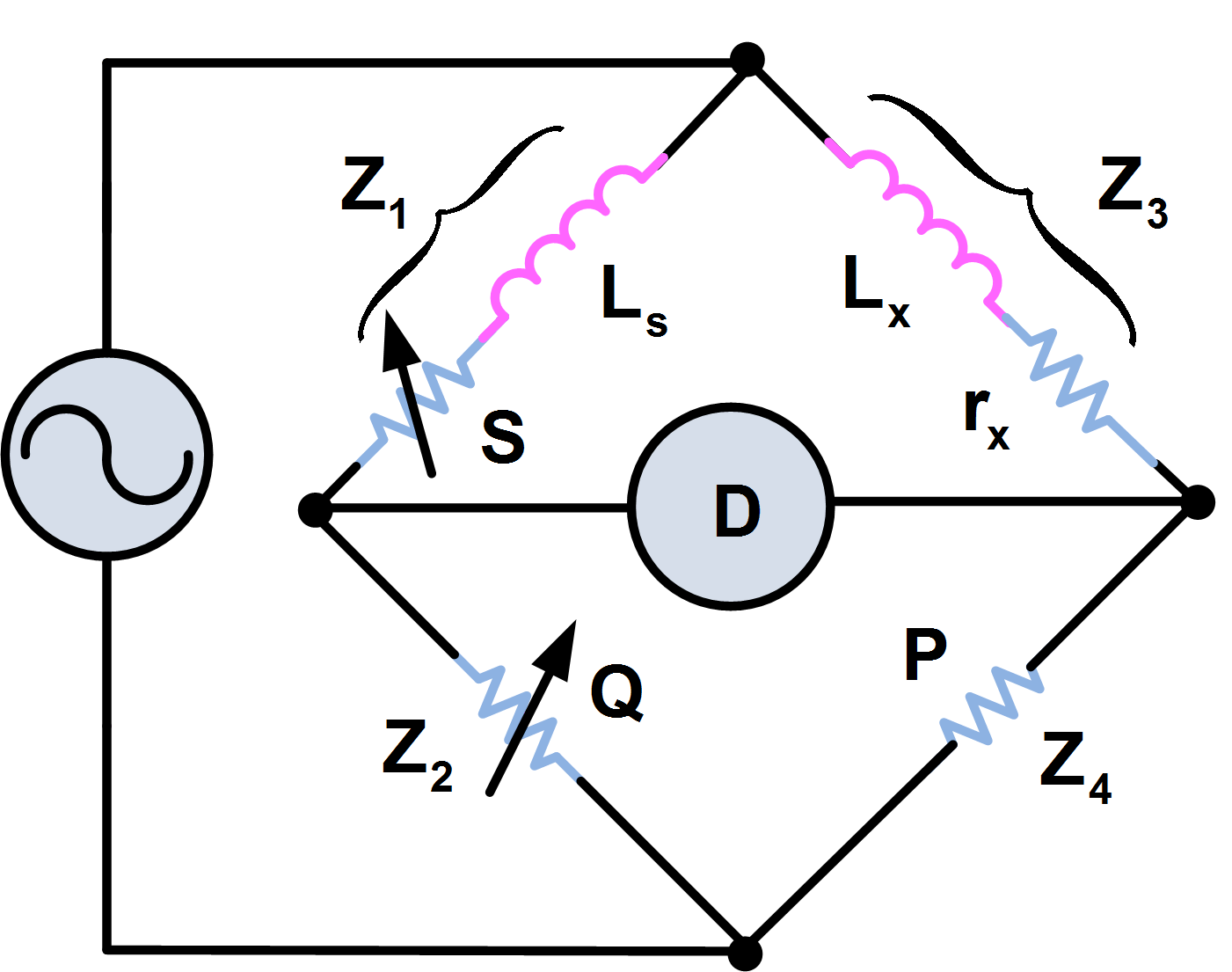
Figure 1. Maxwell Inductance Bridge Circuit Diagram
A disadvantage of this bridge is that the standard inductors are larger and difficult to manufacture than standard capacitors. Consequently, a variation of this circuit, known as the Maxwell-Wein Bridge, is most often employed for inductance measurement.
The circuit of the Maxwell-Wein Bridge is shown in Figure 2.
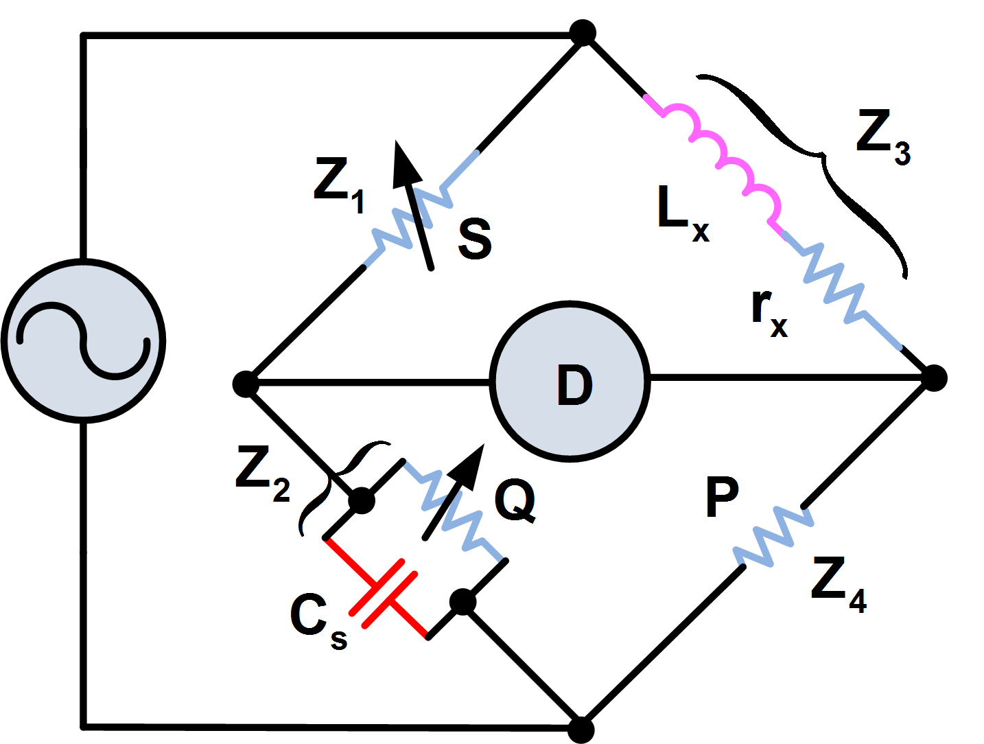
Figure 2. Maxwell-Wein Inductance Bridge Circuit
Lx is the unknown inductance to be measured, and rx is the resistance of its windings. Cs is again a precise standard capacitor, and P is a standard resistor. Q and S are accurately adjustable resistors.
Maxwell Inductance Bridge Working Principle
The Maxwell Inductance Bridge consists of a four-arm AC bridge network:
- Unknown Inductor (Lx): The inductance to be measured. It includes a series resistance (rx) representing the winding resistance of the coil.
- Standard Capacitor (Cs): A precise reference capacitor used in one arm of the bridge. Capacitors are easier to manufacture with high accuracy compared to inductors.
- Standard Resistors (P, Q, S): High-precision resistors used for adjusting and balancing the bridge.
The overall circuit is a modification of the series resistance-capacitance bridge, with inductors replacing capacitors in two of the arms.
The Maxwell Inductance Bridge operates based on the principle of impedance balance. At balance, the ratio of impedances in one pair of opposite arms equals that in the other pair:
\[\frac{{{Z}_{1}}}{{{Z}_{2}}}=\frac{{{Z}_{3}}}{{{Z}_{4}}}\]
Therefore,
\[\begin{matrix} \frac{S}{{}^{1}/{}_{(\frac{1}{Q}+j\omega {{C}_{s}})}}=\frac{{{r}_{x}}+j\omega {{L}_{x}}}{P} & \cdots & (1) \\\end{matrix}\]
Or
\[S(\frac{1}{Q}+j\omega {{C}_{s}})=\frac{{{r}_{x}}+j\omega {{L}_{x}}}{P}\]
\[\begin{matrix} \frac{S}{Q}+j\omega {{C}_{s}}S=\frac{{{r}_{x}}}{P}+\frac{j\omega {{L}_{x}}}{P} & \cdots & (2) \\\end{matrix}\]
Equating the real and imaginary terms:
\[\begin{matrix} \frac{S}{Q}=\frac{{{r}_{x}}}{P} & \cdots & (3) \\\end{matrix}\]
And
\[\omega {{C}_{s}}S=\frac{\omega {{L}_{x}}}{P}\]
Formula for Unknown Inductance
\[\begin{matrix} {{L}_{x}}=P{{C}_{s}}S & \cdots & (4) \\\end{matrix}\]
Once again it is seen that the supply voltage and the frequency are not involved in the balance equations for the bridge. This is not always the case with AC bridges; indeed, one particular bridge can be used to measure the frequency of the supply in terms of the bridge components’ values at balance.
One significant advantage of the Maxwell Inductance Bridge is its frequency independence. The balance equation for Lx is independent of the supply voltage and frequency. This ensures consistent and accurate measurement without requiring specific frequency conditions. However, this frequency independence is not common to all AC bridges, making the Maxwell Bridge particularly robust for practical use.
Maxwell Inductance Bridge Advantages
The Maxwell Inductance Bridge offers several benefits:
- Ease of Use: It simplifies inductance measurement by using a standard capacitor, which is easier to handle and calibrate.
- High Precision: Accurate results can be achieved with high-quality components.
- Flexibility: Suitable for inductors with medium Q-factors, making it useful in many laboratory and industrial applications.
- Stable Calibration: Capacitors maintain their characteristics better over time compared to inductors, ensuring long-term reliability.
Maxwell Inductance Bridge Limitations
While effective, the Maxwell Inductance Bridge has some limitations:
- Dependence on High-Quality Components: Accurate measurements require precise standard capacitors and resistors.
- Unsuitability for Low Q-Factor Inductors: The method is not ideal for measuring inductors with very low Q-factors (e.g., lossy inductors).
- Bulky Components: Standard capacitors and precision resistors can add to the circuit’s size, especially for large-value inductance measurements.
Maxwell Inductance Bridge Key Takeaways
Understanding the operation and applications of the Maxwell Inductance Bridge and the Maxwell-Wein Bridge is crucial for achieving accurate and reliable inductance measurements in practical settings. These methods are important because they allow precise measurement using standard, stable components like capacitors and resistors, which are easier to manufacture and maintain compared to inductors. Their frequency independence, high precision, and flexibility make them highly valuable tools in laboratories, industrial testing, and electronic circuit development, where accurate characterization of inductors directly impacts the performance and reliability of electrical systems.