This article provides an overview of proximity sensors, explaining how they detect the presence or absence of objects across various industrial and consumer applications. It reviews major proximity sensor types—including Hall-effect, inductive, capacitive, ultrasonic, and contact-based switches—highlighting their operating principles and typical use cases.
A proximity sensor measures the presence or absence of an object. Proximity sensors are widely used in products in various industries, including automotive, appliance, and manufacturing. Examples include sensors to detect seatbelt on/off status in vehicles, door and lid open/close detection in appliances, obstacle presence in closing powered doors, rotor angle position in brushless DC motors, and end-of-travel detection in pneumatic actuators.
There are several types of proximity sensors, including Hall-effect, inductive, capacitive, photoelectric, ultrasonic, and switch-type contact.
Hall-Effect Sensors
A Hall-effect sensor is a non-contact type sensor that is based on the Hall effect, which was discovered by Hall in 1877. The Hall effect states that a voltage difference is developed in a current-carrying conductor when subjected to a magnetic field. This voltage is perpendicular to both the current and the magnetic field.
The Hall effect is illustrated in Figure 1. Figure 1(a) shows a thin conducting plate in which a current is flowing. In the absence of an external magnetic field, there is no voltage difference across the sides of the plate. However, when a magnetic field is applied perpendicular to the direction of the current, as shown in Figure 1(b), it exerts a force on the charge carriers in the conductor. This force causes a redistribution of these charge carriers, leading to an accumulation on one side and a deficiency on the other, which results in a voltage difference known as the Hall voltage. This voltage can be described by
$${\underset{V}{\rightarrow}_{H}}=\frac{\underset{I}{\rightarrow}_{\times } \underset{B}{\rightarrow}}{n\times q\times d} (1)$$
where I is the current vector, B is the magnetic flux vector, n is the charge carrier density, q is the elementary charge, and d is the thickness of the conductor. Note that the voltage difference is perpendicular to both the current flow and the magnetic flux direction. The amount of voltage that is generated is typically small, and a differential amplifier is used to amplify this voltage signal.
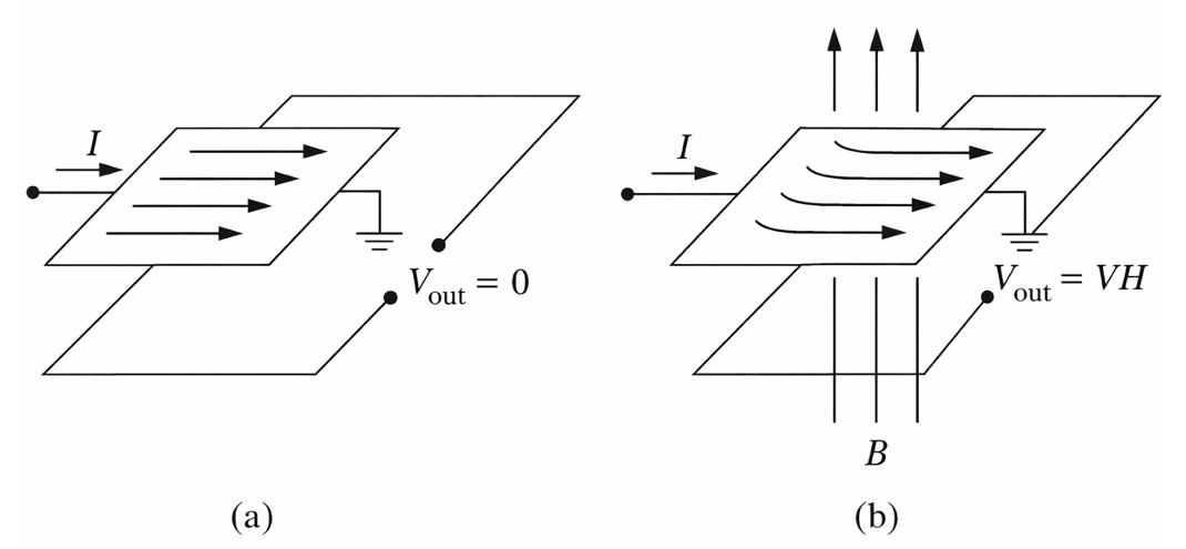
Figure 1. Illustration of the Hall effect: (a) current in a conductor with no magnetic field applied and (b) current in a conductor with a magnetic field perpendicular to the current flow
Hall-effect sensors are solid-state sensors that are constructed using semiconductor processing techniques. A Hall-effect proximity sensor consists of two pieces: a stationary sensor package and a magnet that is attached to the object whose presence needs to be detected, as seen in Figure 2. The magnet and the sensor package are separated by an air gap.
Unipolar and Bipolar Hall-Effect Sensors
There are two variations of Hall-effect sensors: unipolar and bipolar.
- In the unipolar design, when a south pole magnet approaches the designated package surface within a specified distance, the sensor turns ON. When the magnet is removed, the sensor turns OFF.
- In the bipolar design, the removal of the south pole does not cause the sensor to turn OFF; a north pole needs to approach the sensor to cause the sensor to switch OFF. A typical circuit for a Hall-effect digital proximity switch is shown in Figure 3.
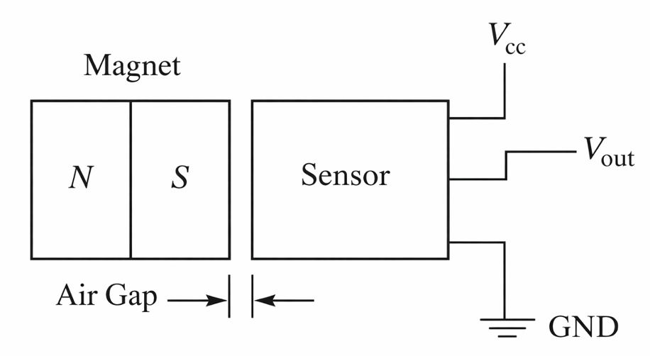
Figure 2. Hall-effect proximity sensor circuit diagram
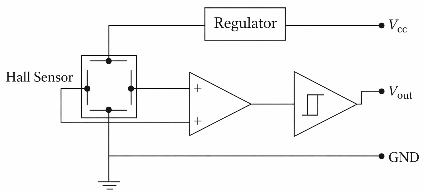
Figure 3. Hall-effect proximity switch wiring
In this circuit, the supply voltage is connected to the Hall sensor through a voltage regulator. The Hall-effect voltage is processed through a differential op-amp to amplify the voltage generated by the Hall-effect sensor. The output of the differential op-amp is connected to a Schmitt trigger. The Schmitt trigger compares the output voltage from the differential op-amp to a preset voltage level.
- If the output voltage exceeds the preset voltage, the switch output will be set high.
- When the differential op-amp output falls below a threshold level, the switch output will be set low.
The hysteresis of the Schmitt trigger is used to reduce the sensitivity of the sensor to noise and false triggering. The Schmitt trigger output can also be connected to a switching transistor.
An example of a commercially available Hall-effect sensor is shown in Figure 4.
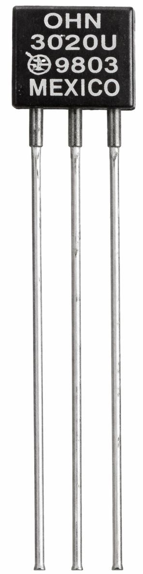
Figure 4. Commercially available Hall-effect sensor
Inductive Proximity Sensors
Inductive proximity sensors utilize the eddy current generated when a metallic element is placed within the proximity of an electromagnetic coil. The principle of operation of the sensor is shown in Figure 5.
- The sensor has an oscillator circuit that creates a magnetic field in front of the sensor through the coil inductance.
- When a metal target enters this magnetic field, it changes the magnetic field in the oscillator. This causes a swirling current, called an eddy current, to be generated in the coil.
- The change in current in the coil is detected by a circuit that is connected to a switching amplifier.
The oscillator, the current detection, and the switching-amplifier circuits are all normally housed within the resin of the sensor.
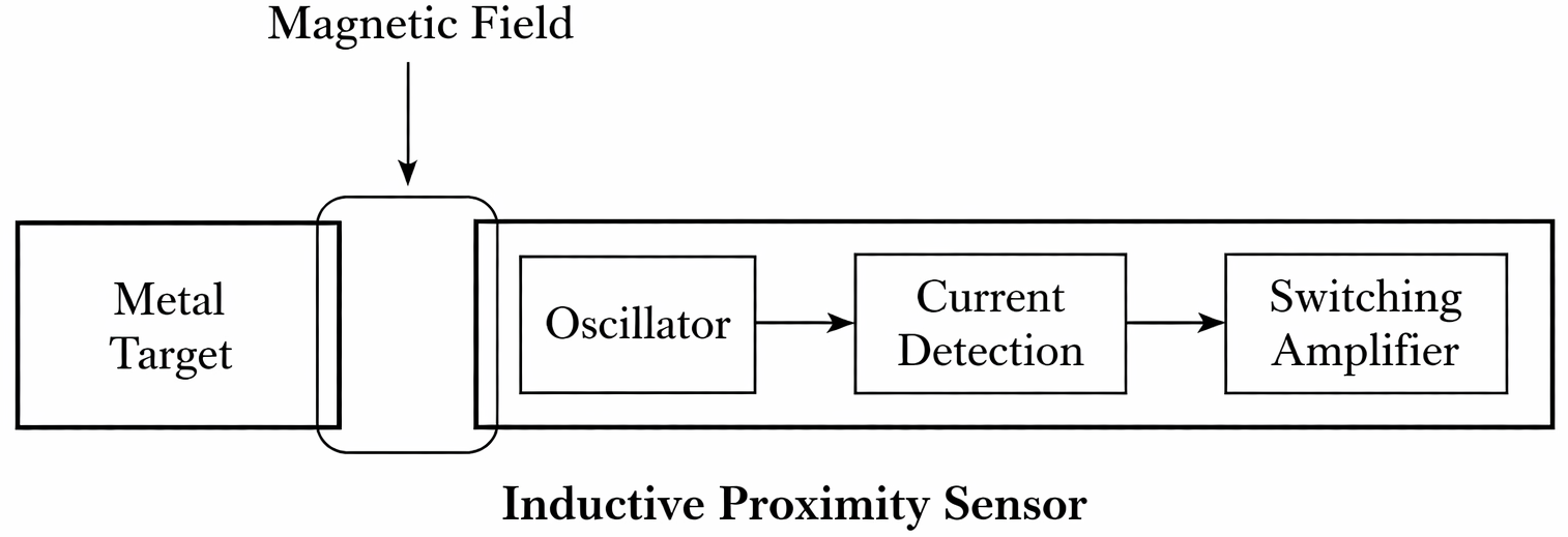
Figure 5. Inductive proximity sensor operation diagram
Figure 6(a) shows commercially available inductive proximity sensors. While most inductive sensors are cylindrical, rectangular-shaped sensors are also available. Cylindrical-shaped sensors are available with threaded or flat surfaces. Some units have an LED built into the sensor head to indicate object detection. The sensor electronics can be built into the sensor head or located separately from the head.
Unlike Hall-effect sensors, in which the target material is magnetic, inductive proximity sensors detect all metal objects at distances ranging from 1 to 30 mm. The larger the size of the sensor, the longer the detection range is.
Standard inductive proximity sensors have a reduced detection range for nonferrous metals (such as copper, aluminum, and brass) than for ferrous metals (such as steel and iron, see Figure 6(b)). For non-metal objects, capacitive-type sensors can be used instead.
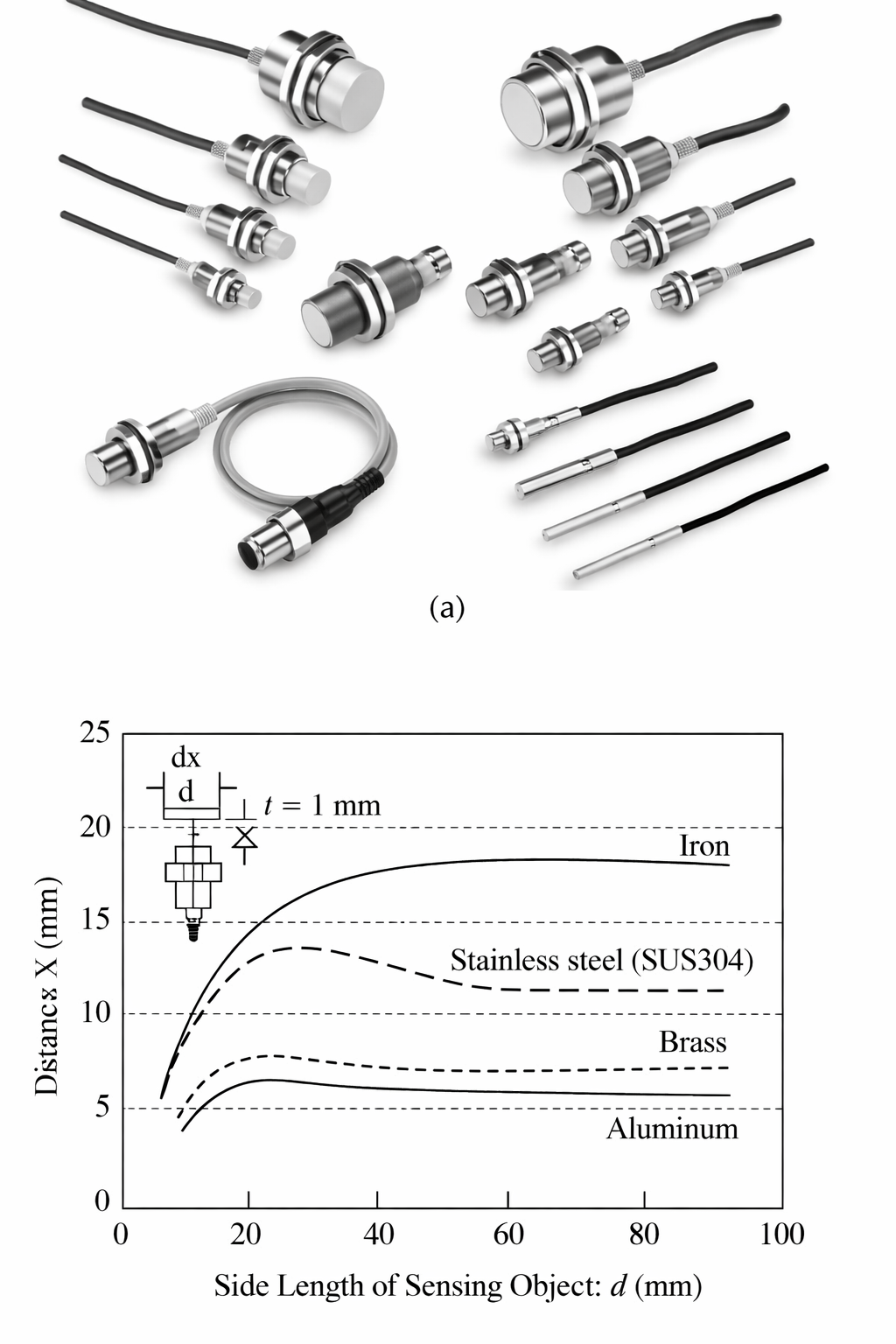
Figure 6. (a) Commercially available inductive proximity sensors and (b) detection range for a typical sensor for different metals
Inductive proximity sensors, as all on/off sensors or switches, are available in either NO or NC switch configuration. Furthermore, wiring to these sensors is available in either a two- or three-wire configuration. In the three-wire configuration, the output is available with either NPN or PNP transistor configuration. Example 1 illustrates the wiring circuit for a two-wire NO inductive proximity sensor used as a switch in a relay circuit.
Example 1 Two-Wire Inductive Proximity Sensor
Draw a wiring circuit for a two-wire NO inductive proximity sensor used as a switch in a relay circuit. The output circuit of the sensor is shown on the left side of Figure 7.
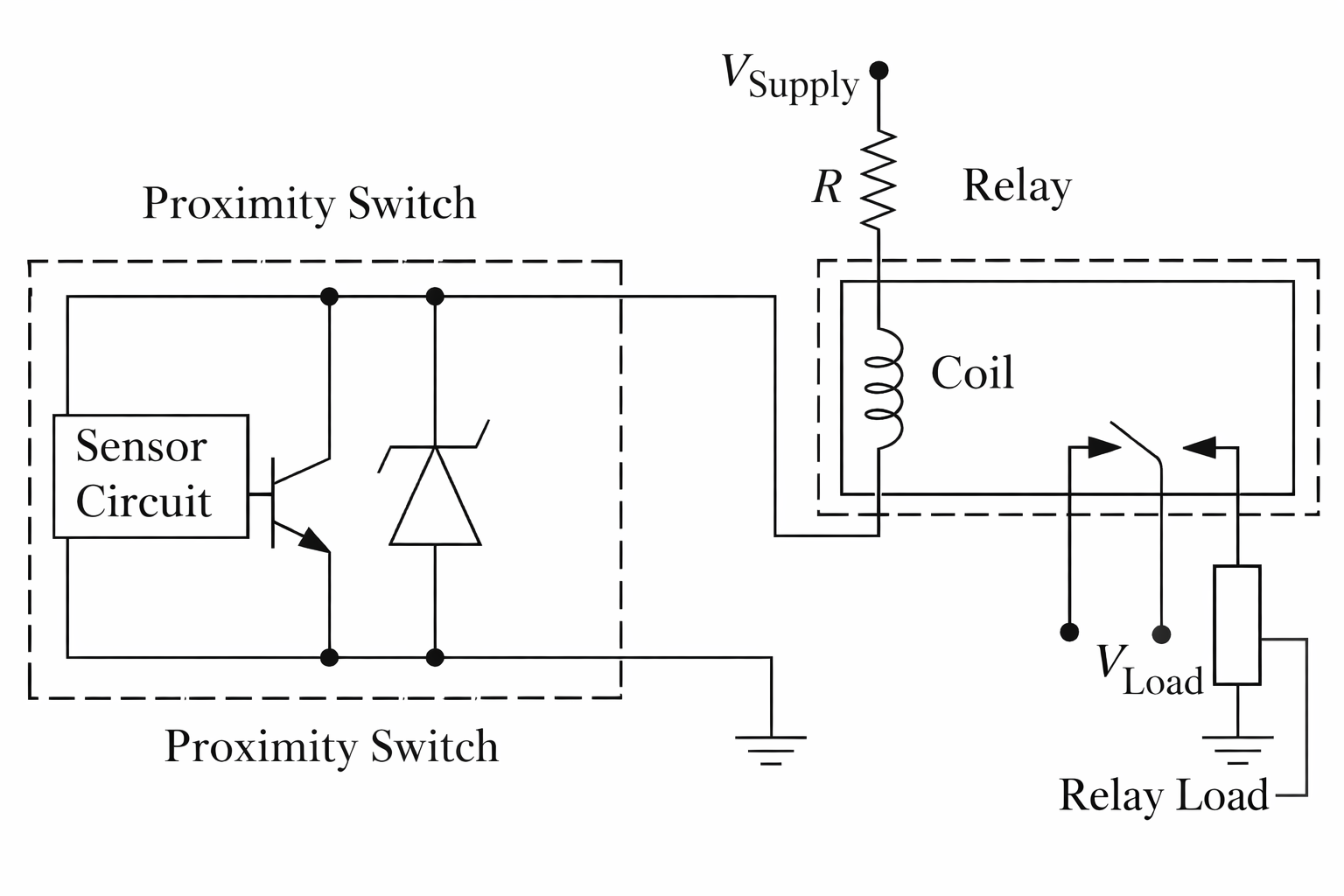
Figure 7. Wiring for a two-wire inductive proximity sensor
Solution
The circuit is included in Figure 7. The supply voltage (typically 24 VDC) is connected to one end of the relay coil through a resistor R. The value of R is chosen to meet the current limit through the coil.
The resistor R and the relay coil resistance will act as the load resistor on the sensor output circuit. The other end of the relay coil is connected to the load input on the sensor circuit. The other wire of the sensor circuit is connected to ground.
Since this is a normally open sensor switch, the relay coil will not energize unless an object came within the detection range of the sensor. The detection of an object will thus cause the relay switch to close and to transmit power to the load connected to the relay.
Inductive proximity sensors are also used to detect vehicle presence at intelligent traffic lights. These traffic lights are commonly used in rural or country roads where the traffic volume is variable.
- The sensor takes the form of a wire loop that is placed in a groove that is cut into the asphalt surface.
- When a vehicle passes over the loop, the inductance of the loop is affected by the presence of the metallic body of the car.
- The electronics sense the vehicle’s presence and use this information to adjust the traffic light timing.
Capacitive Proximity Sensors
Capacitive proximity sensors and inductive proximity sensors may appear similar in appearance, but they operate based on different principles.
Capacitive proximity sensors operate based on the principle of measuring changes in capacitance. The capacitive sensor contains a conductive plate or electrode that generates an electrostatic field around it, unlike inductive proximity sensors, which generate a magnetic field.
- When a target object comes near the sensor, it alters the electrostatic field, leading to a change in capacitance between the sensing electrode and the target object. The capacitance increases as the object gets closer to the sensor.
- The sensor is equipped with an oscillator circuit that generates an oscillating electrical signal.
- The change in capacitance caused by the target object alters the frequency or amplitude of the oscillator’s output signal.
- The sensor’s electronics process the changes in the oscillator’s output signal and convert them into a usable digital switching output signal that indicates the presence or absence of the target object.
In contrast to inductive proximity sensors, capacitive sensors can detect a wide range of materials, including both ferrous and non-ferrous metals as well as non-metal objects such as liquids and plastics. They also offer a larger detection range compared to inductive sensors. Additionally, capacitive sensors provide the flexibility to adjust their sensitivity for detecting specific targets, which is not possible with inductive sensors.
Figure 8 shows two examples of capacitive proximity sensors. Figure 8(a) shows a capacitive sensor with a detection range of up to 25 mm and with adjustable sensitivity. Figure 8(b) shows a sensor specifically designed for detecting the liquid level in a pipe. This sensor is unaffected by the color of the pipe or liquid.
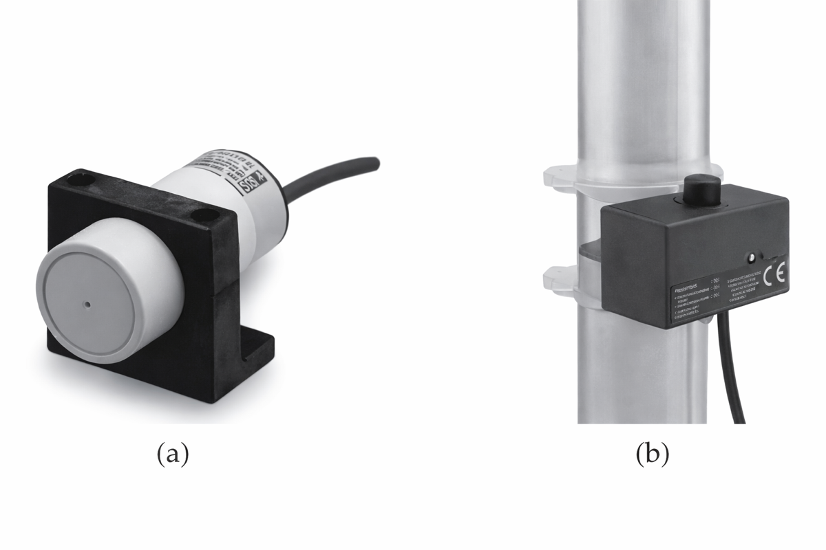
Figure 8. (a) Long-distance capacitive sensor with adjustable sensitivity (Model E2K-C) and (b) liquid-level capacitive sensor (Model E2K-L)
Comparable to inductive proximity sensors, all on/off sensors or switches, are available in either NO or NC switch configuration. Furthermore, wiring to these sensors is available in either a two- or three-wire configuration. In the three-wire configuration, the output is available with either NPN or PNP transistor configuration.
Ultrasonic Sensors
Ultrasonic sensors operate by emitting sound waves and detecting their reflections to discern the presence, absence, or distance of objects. Among the common types are through-beam ultrasonic sensors, which utilize separate transmitter and receiver units. The receiver identifies any disruption in the continuous sound wave sent by the transmitter, making it especially sensitive and reliable for object detection.
Proximity (or diffuse) ultrasonic sensors combine the transmitter and receiver into a single unit. These sensors ascertain the presence or distance of an object by gauging the travel time of a high-frequency sound wave that reflects off an intervening object.
- The sensor’s transducer periodically emits a burst of sound at high frequencies (30 kHz or higher) for a brief interval.
- Post-transmission of this burst signal, the sensor transitions to receiving mode, capturing the time of the echoed signal’s arrival.
- With the speed of sound known in the transmission medium, such as air, the interval between the source signal’s transmission and the reflected signal’s receipt is used to deduce the object’s position.
Retro-reflective ultrasonic sensors are designed such that, in the absence of any intervening object, sound waves return to the sensor from a designated reflector. The appearance of an object between the sensor and the reflector interrupts this reflection, activating the sensor.
In comparison to inductive proximity sensors, ultrasonic sensors boast a significantly larger detection range (measured in meters versus millimeters). However, some ultrasonic sensors might struggle to detect very close objects (just a few centimeters away) due to potential overlap between transmission and reflection times. The detectability of objects in relation to the frequency of the sound signal is such that higher frequencies are better suited for smaller objects, while lower frequencies can detect larger ones.
Ultrasonic proximity sensors can offer an analog output voltage related to an object’s distance from the sensor or provide a binary output indicating the object’s presence or absence within a predefined zone. Common applications include liquid-level measurements and production-line object detection.
A noteworthy characteristic of ultrasonic sensors is their indifference to the color, transparency, or lighting conditions of the detected object. However, they may falter when tasked with detecting materials that absorb high-frequency sound, such as cotton or sponge.
A commercial ultrasonic sensor for use in industrial applications is shown in Figure 9. This through-beam sensor has a detection range of 500 mm and is suitable for the detection of transparent films, transparent bottles, and other similar workpieces.
A low-cost proximity ultrasonic sensor (HC-SR04) that is widely used in educational mobile robots to detect obstacles and walls is shown in Figure 10. This sensor has a detection range of up to 4 m, operates at a frequency of 40 kHz, and is composed of two ultrasonic transducers, one to transmit ultrasonic sound pulses and the other to receive the reflected waves. There are several libraries, such as NewPing, available for the Arduino platform to process the signals from this sensor, which simplifies the use of this sensor.
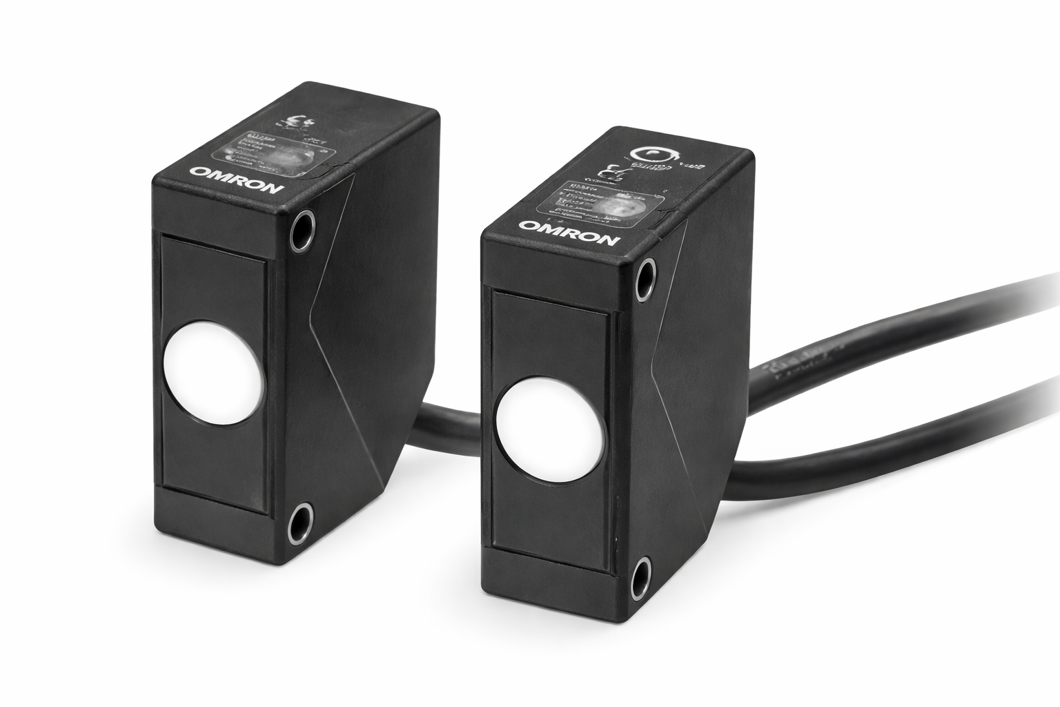
Figure 9. Compact ultrasonic sensor (Model E4E2)
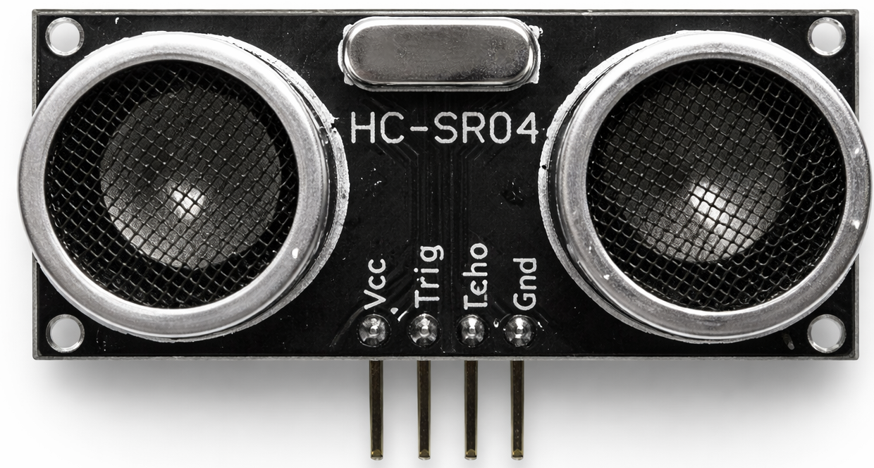
Figure 10. HC-SR04 ultrasonic sensor
Contact-Type Proximity Sensors
Contact mechanical switches known as ‘limit switches’ are used in robotic and machine tool applications to detect the end of travel for a moving axis. They are also used in conveyor systems and transfer machines to detect objects and packages, as well as in elevators, scissor lifts, and safety guarding applications.
These sensors are available with different ‘operator’ types that provide the interface between the contact object and the switch mechanism. These types include a roller plunger, a dome plunger, a roller lever, a telescoping arm, and a short lever. Figure 11 illustrates a few of these operator types. These sensors are rugged and can be used in harsh situations.
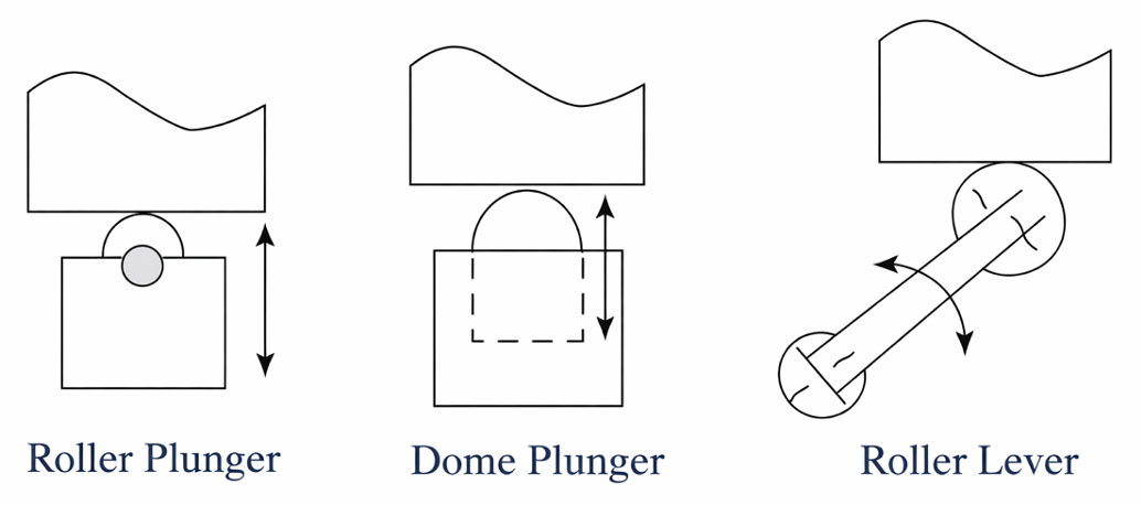
Figure 11. Operator types for limit switches
Key Takeaways
Proximity sensors play a critical role in modern automation, safety, and control systems by enabling reliable object detection without complex mechanical contact. From industrial manufacturing and robotics to automotive systems, consumer appliances, and process control, selecting the appropriate sensor type—Hall-effect, inductive, capacitive, ultrasonic, or contact-based—directly impacts performance, durability, and system efficiency. Understanding their operating principles and limitations allows engineers to design robust detection systems that improve operational safety, reduce maintenance, enhance precision, and support smarter, more responsive applications across a wide range of industries.