The article provides a step-by-step overview of designing a stand-alone solar PV system, covering essential stages such as conducting an energy audit, evaluating the site, sizing the PV array, and determining cabling and battery needs. It emphasizes system efficiency, potential energy savings, and practical considerations for component selection and installation.
Designing a solar PV system requires a systematic approach. The first step in sizing a stand-alone solar PV system is to perform an energy audit, looking for places to save energy.
The power requirements are evaluated as part of the audit, and the site is evaluated for the expected solar input. From this, the basic system is designed.
In this section, you will go through the steps of the basic process for designing a stand-alone system.
Design Steps for a Stand-Alone PV System
The following steps provide a systematic way of designing a stand-alone PV system:
- Conduct an energy audit and establish power requirements.
- Evaluate the site.
- Develop the initial system concept.
- Determine the PV array size.
- Evaluate cabling and battery requirements.
- Select the components.
- Review the design.
Step 1: Conduct an Energy Audit and Establish Power Requirements
The load requirements should be the starting point in determining a stand-alone system.
Start by calculating the power requirement for each AC electrical load and multiplying by the average number of hours it is powered on each day (Wh/day), which represents energy/day. A spreadsheet is a useful tool for developing this analysis.
Table 1 shows how a summary of appliances and their usage can give a reasonable estimate of the load requirement; the load is calculated for each month to account for seasonal variations.
From this analysis, the average daily use can be determined for a one-year interval. For the month shown, the average daily energy use is 10.79 kWh, which is the energy the solar system will need to provide.
The analysis can also reveal opportunities for conserving energy and/or by switching part of the load to other sources, such as propane instead of electricity, and also the savings expected for replacing incandescent bulbs with compact fluorescent bulbs or LED lighting.
Standby Power
An often-overlooked load is the standby power used by many electronic devices.
Standby power is the power to keep devices ready.
In many devices (televisions, computers, printers, phones, etc.), a certain amount of power is used when the device is plugged in but not in service. This power can add up.
In the average US household, it is estimated that standby power accounts for a constant load between 40 and 60 W, equivalent to leaving a light on day and night. Removing unnecessary loads like these can reduce the requirements shown in the load analysis and are almost always cost-effective.
| AC Load Description | Quantity | Power Rating (W) | Time on per Day (h/da) | Energy Used (Wh/day) |
| Refrigerator | 1 | 450 | 8 | 3,600 |
| Washing machine | 1 | 500 | 0.5 | 250 |
| TV | 2 | 100 | 3 | 600 |
| Lights (incandescent) | 4 | 60 | 6 | 1,440 |
| Lights (fluorescent) | 5 | 30 | 10 | 1,500 |
| Toaster oven | 1 | 1,500 | 0.5 | 750 |
| Microwave oven | 1 | 1,000 | 0.4 | 400 |
| Ceiling fans (medium speed) | 3 | 25 | 10 | 750 |
| Computer | 2 | 125 | 4 | 1,000 |
| Printer | 1 | 400 | 0.25 | 100 |
| Miscellaneous loads | 1 | 200 | 2 | 400 |
| TOTAL 5 = | 10,790 |
Table 1 Load Requirement Analysis for a Typical Month Using a Spreadsheet
Step 2: Evaluate the Site
The site should be reviewed to determine the feasibility of a solar system. Look for possible shading problems and potential installation problems.
Site data for insolation is available from the National Renewable Energy Labs for the United States and from private companies for other locations.
The word insolation comes from “incident solar radiation” and is a measure of the energy received on a surface in a specific amount of time.
From the data, the average hours of peak sunlight (equal to or greater than 1,000 W/m2) can be estimated for each month of the year. The monthly solar irradiance can vary considerably, so this needs to be taken into account when designing a system.
At the specific site, consider possible locations for solar modules and consider the effect of wind or snow loading of arrays and installation issues (roof condition, structural supports, and strength, etc.) or future maintenance issues (cleaning, snow or wind loads, etc.).
Generally, modules can be installed on a south-facing roof, a ground framework, or a pole. A single shaded PV module in a series arrangement restricts the current to the other modules and can seriously affect system performance.
To analyze a site for possible shading problems, a device like the Solar Pathfinder™ is useful (see Figure 1).
The Solar Pathfinder uses a polished, transparent dome that shows a reflected panoramic view of the site. Trees, buildings, or other obstacles to the sun are seen as reflections on the surface of the dome.
The sun’s path is also shown as lines on the dome, so a proposed location can be evaluated for shading problems for the entire year.
Using analysis software from Solar Pathfinder™, a custom report can be generated that shows the percentage of shading expected for each month and the expected performance of an array.

Figure 1 Typical Results from the Solar Pathfinder™. This device can show potential shading problems.
To avoid problems with a shaded module that is in series with other modules, or one that has failed, use bypass diodes. Some modules come equipped with one or more bypass diodes. They provide a current path around the module or parts of the module when there is low voltage.
When operating normally, the bypass diodes are reverse-biased, effectively removing them from the circuit. If the voltage across a diode is less than about 0.7 V, the bypass diode becomes forward-biased and provides a current path.
Figure 2 shows how bypass diodes are connected in a group of three series modules, each with one bypass diode.
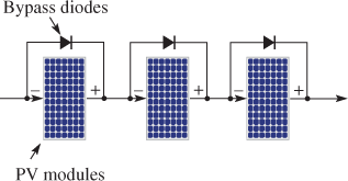
Figure 2 Bypass diodes allow current to bypass a shaded module or one that has failed.
Installation problems include a roof that is not oriented due south or a roof that has a slope that is too steep or is too flat.
Ideally, the modules should be perpendicular to the sun’s rays, but this is not possible for fixed arrays or most roof-mounted arrays.
In general, a flat-plate collector should be tilted at an angle that is equal to the latitude to optimize the greatest average radiation, although some people prefer to optimize the winter months by tilting the modules at a higher angle.
Ground-mounted and pole-mounted installations allow greater accessibility for making seasonal adjustments to the tilt angle, which can add a few percentage points to the overall energy obtained.
For roof installations, mounting brackets can be selected that optimize the tilt angle toward the south, even if the roof is not oriented in that direction (see Figure 3).
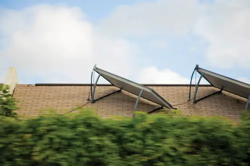
Figure 3 Roof Installation with Mounting Brackets. Modules can be oriented south using special mounting brackets.
Step 3: Develop the Initial System Concept
Having established the resource(s) available and the power requirement, an initial system concept can be developed. The system is evaluated for different operating voltages, which affect the size of the cables and the components selected.
Consideration is given to system redundancy, battery backup, and overall cost. In some cases, two or more small systems may be preferable to a larger system.
System losses need to be accounted for: A typical system (not including batteries) is less than 80% efficient due to losses in cables and connectors, inverter losses, temperature changes from ambient, soiling of the array, and so on.
Battery efficiency is another large source of loss because the energy returned from the battery is typically only 80% of the original energy stored. Thus, in a battery-backed system, the overall efficiency may be only 60%.
Step 4: Determine the PV Array Size
From the projected resource(s), power requirement, and estimated efficiency, the size of the array can be determined. The power requirement for the array, in watts, is estimated for each month by the following equation:
${{P}_{array}}=W\times {{t}_{solar}}\times {{\eta }_{sys}}$
Where
Parray represents the peak power, in watts (W), from the array (based on the manufacturer’s module label)
W is the daily energy requirement in, watt-hours (Wh)
tsolar is the average hours (h) of peak sunlight for the month
𝜂sys is the overall efficiency of the system
This efficiency does not include the inherent inefficiency of PV modules in converting sunlight to electricity but is due to losses in the system, such as inverters, cabling, battery charging losses, and conditions differing from the rated test conditions (such as temperature or irradiance).
Notice that less power is required from the array if the system is more efficient, so overall efficiency is important.
PV System Power Calculation Example 1
A certain site has an average of 5 hours of peak sunlight per day in January. If 11 kWh is required on an average January day from a grid-free system, what peak power is required from the array? Assume the system is 60% efficient, which represents a typical residential system.
${{P}_{array}}=W\times {{t}_{solar}}\times {{\eta }_{sys}}=11,000\,\times 5\times 0.60=3670\,W=3.67\,kW$
Choose modules that will provide at least this much power: 18 modules of 215 W is 3.87 kW.
Step 5: Evaluate Cabling and Battery Requirements
Determine the wire size required from the initial system concept. For a given power, the current (and hence the required wire size) is smaller as the voltage is higher.
In general, smaller diameter wire costs less but is rated for less current and drops more voltage. Note that listed wire capacity needs to be significantly derated for higher temperatures due to wiring on roofs and if the wires are bundled or in conduit.
Generally, the size of the wiring is determined so that voltage drops are in the range of 2% or 3%, but relevant codes should be consulted in determining wiring requirements.
PV System Wire Sizing Example
Assume that 18 panels (modules) of the type are selected for the system in Example 1. Their configuration matches system 5 in Figure 1. Assume the panels are wired in six parallel groups, with each having three panels in series that are combined at a combiner box, and the output is sent to a charge controller.
What is the minimum wire size needed for the series groups to the combiner box and the parallel groups from the combiner box? Assume you need to derate the wire so that it carries 50% of its normal rating.
Solution
In the series groups, the current is the same in all panels, so the maximum current is the short-circuit current for one panel, which is specified by the manufacturer as 5.8 A.
From the table, the AWG 16 copper wire has a normal current capacity of 15 A. When a 50% derating factor is applied, the current carrying capacity is 7.5 A, which is sufficient.
After combining the series groups in parallel, the wiring needs to be able to handle 34.8 A (6 × 5.8 A). The minimum wire size with a 50% derating should normally be able to handle 69.6 A (34.8 × 2).
Choose AWG 4 copper wire (rated for 70 A) to meet the minimum requirement.
After determining the wiring size, you need to evaluate the battery requirement. As you know, batteries are connected in series to increase voltage and in parallel to increase capacity.
The battery backup system generally has some combination of a series and parallel arrangement to set the voltage to the required voltage for the system.
Batteries can have very high discharge currents, so disconnect switches and overcurrent devices must be selected with the appropriate ratings.
Disconnect switches are important to isolate the batteries for maintenance or replacement. Also, batteries need to be in a vented and protected enclosure for safety and to avoid access by children or people unqualified to work with the equipment.
Batteries in solar electric systems tend to be regularly charged and discharged, so they need to be deep-cycle types.
Standard automobile batteries have thin plates and are designed for high starting currents, but they are not suitable for solar systems because they are not designed for deep cycling.
Golf cart batteries and larger L-16 traction batteries have thick plates, which are suitable for solar systems. Flooded lead-acid batteries are the most common type of deep-cycle battery, but they must be checked regularly for fluid level and specific gravity, cleaned of any corrosion and refilled as needed with distilled water.
Specific gravity is tested with a hydrometer, which indicates the state of charge. A fully charged lead-acid battery has a specific gravity between 1.25 and 1.28. The fill level is important; the electrolyte should be maintained above the minimum and below the maximum level line on the side of the battery.
Figure 4 shows a typical battery installation for a residential installation. The battery array needs to be installed in a cool, well-ventilated area that is not in the living area; a garage or utility room is common (but very high or very cold temperatures decrease battery life).
Venting releases any hydrogen gas that builds up as a result of charging; hydrogen is less dense than air, so the vent pipe should be high. Batteries should be fully charged when they are put in service to maximize their life.
Charging is complete when the charging current is near zero. Overcharging is dangerous because it can lead to increased hydrogen production and create an explosion hazard.
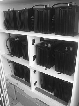
Figure 4 Condensed Battery Installation That Is Still Accessible for Maintenance. Batteries should be arranged to prevent accidentally dropping anything on them. A screened vent is needed in the storage area to release any hydrogen gas.
The capacity of any battery is measured in ampere-hours. The ampere-hour (Ah) is a unit of charge, that is, current multiplied by time. From basic math, 1 ampere-hour is equal to a charge of 3,600 coulombs.
A typical deep-cycle golf-cart battery is rated for 225 Ah at 6 V. The popular L-16 solar battery is rated for 370 Ah at 6 V.
The designer needs to specify the depth of discharge (DOD), which is the ratio of the quantity of charge (measured in ampere-hours) removed from a battery to its rated capacity and can be expressed as a percentage.
Although 80% discharge is sometimes specified by manufacturers, continuous deep discharging leads to shortened battery life; many batteries can be damaged if they are deeply discharged.
Figure 5 shows how battery life for a typical deep-cycle battery depends on the depth of discharge. As you can see, the expected lifetime is shortened by deeply discharging the battery.
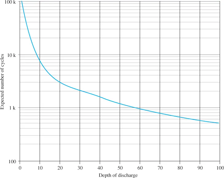
Figure 5 Expected Life Cycle versus Depth of Discharge
Safety Note
Flooded lead-acid batteries can produce hydrogen and oxygen, an explosive combination, so they should never be used indoors or near an ignition source and should always be vented to the outside.
Electrical equipment (inverters, switches, fuses) should not be in their vicinity. Avoid sparks or open flames near batteries and post “no smoking” signs. Wear eye protection and acid-proof gloves when handling batteries.
Have water and baking soda nearby to neutralize any acid spilled from a lead-acid battery and clean up spills immediately.
A reasonable depth of discharge is 50% over a period of days to save on replacement cost (leaving some reserve for emergencies or below-average insolation), but the decision about the number of batteries required depends on various factors, and the depth of discharge varies seasonally.
Depending on the projected weather at the site, the batteries are typically sized for three to five days of autonomy in a grid-free system (no solar input).
Keep in mind that batteries are expensive and have maintenance issues, so the balance between the number of batteries and the cost of the system is always a compromise.
The following formula can be used to determine the required ampere-hours of the batteries:
\[Ah={{W}_{day}}\times {{t}_{store}}\times V\times {{B}_{dod}}\times {{\eta }_{inv}}\]
Where
Ah is the required ampere-hours (Ah) from the batteries
Wday is the daily energy requirement per day, in watt-hours/day (Wh/d)
tstore is the backup time required, in days (d)
V is the dc system voltage to the inverter, in volts (V)
Bdod is the battery’s maximum depth of discharge, expressed as a fraction
𝜂inv is the efficiency of the inverter and cabling, also expressed as a fraction
PV System Battery Sizing Example 3
Assume that the system described in Example 1 is a 24 V system (from the charge controller). Three backup days are required.
How many L-16 deep-cycle batteries (rated at 6 V, 390 Ah), are required to provide the three days of backup if the DOD is 50% and the inverter/cables are 95% efficient?
\[Ah={{W}_{day}}\times {{t}_{store}}\times V\times {{B}_{dod}}\times {{\eta }_{inv}}=(11,000\,Wh/d)\times (3d)\times (24\,V)\times (0.5)\times (0.95)=2,895\,Ah\]
The system operates on 24 V, so four 6 V batteries need to be connected in series to give the required 24 V.
Each bank of four L-16 batteries will have a 390 Ah rating at 24 V. Eight banks of four series batteries will produce 8 × 390 Ah = 3,120 Ah, which exceeds the requirement for three days of autonomy.
Hence, a total of 32 batteries are required for this system.
Step 6: Select the Components
Once the system is analyzed, the components are selected. For a stand-alone system, you will generally need the PV modules, combiner boxes, a charge controller, battery backup, and an inverter.
In addition, the system will require mechanical and electrical hardware components, which includes mounting hardware, racks, connectors, junction boxes, disconnect switches, fuse holders, contactors, surge arrestors, wiring and conduit, and other parts.
Lead-acid batteries are the dominant energy storage technology, but the more expensive lithium-ion batteries have important advantages for renewable energy systems that may make them competitive with lead-acid batteries in the future. These advantages include longer lifetime and higher efficiency.
They can also be charged and discharged many more times than lead-acid batteries can be. If the cost can be made more competitive, lithium-ion batteries may replace lead-acid batteries as the main storage technology in the future.
Step 7: Review the Design
After completion, the design must be reviewed to ensure that the specifications for the system have been met and that all components are operating within their design limits.
After completing the design review, plans must be submitted to appropriate government agencies for approvals and permits before any work is done. The electrical utility must approve any connection that is made to the electrical grid.
Solar PV System Review Questions
- How does a bypass diode prevent a complete failure if one module in a series string fails?
- As a rule of thumb, what is the best angle to tilt a fixed flat-plate collector?
- What measurement unit is used to measure the capacity of a battery?
- What is meant by the term depth of discharge?
Answers
- A failed module with no output normally would block current from the other modules. A diode can provide a current path around the failure and is active only if the module in question has < 0.7 V.
- If the tilt is not adjustable, it normally will be set for the latitude or slightly more to optimize the collection in winter.
- The ampere-hour (Ah)
- DOD is the ratio of the quantity of charge (usually in ampere-hours) removed from a battery to its rated capacity and can be expressed as a percentage.
Stand Alone Solar PV System Key Takeaways
Designing a stand-alone solar PV system involves a series of carefully coordinated steps—from conducting an energy audit to evaluating site conditions, sizing the PV array, and determining cabling and battery needs. Each of these steps plays a critical role in optimizing the system’s performance, cost-efficiency, and reliability. These design principles are crucial in practical applications such as powering off-grid homes, remote telecommunication sites, rural clinics, and emergency backup systems, where access to the electrical grid is limited or nonexistent.