The article provides an overview of wind turbine blade aerodynamics, focusing on how lift and drag forces influence blade movement and energy conversion. It also explains key concepts such as angle of attack, tip speed, tip speed ratio (TSR), and blade twist to optimize turbine efficiency.
The wind turbine blade on a wind generator is an airfoil, as is the wing on an airplane. By orienting an airplane wing so that it deflects air downward, a pressure difference is created that causes lift. On an airplane wing, the top surface is rounded, while the other surface is relatively flat, which helps direct air flow.
The blade on a wind turbine can be thought of as a rotating wing, but the forces are different on a turbine due to the rotation. This section introduces you to important concepts about turbine blades.
A turbine blade is similar to a rotating wing. Differences in pressure cause the blades to both bends and rotate.
In normal operation, the rounded front portion of the blades is oriented in the direction of rotation and the flat portion faces the wind.
The front of the blade is referred to as the leading edge and the back is referred to as the trailing edge, as illustrated in Figure 1a.

Figure 1 Air Moving Past a Turbine. (a) The rounded leading edge is oriented in the direction of rotation. (b) A lift force is created by pressure differences that are perpendicular to the apparent wind direction. This force tends to bend the blades and create a smaller rotational force.
Lift and Drag
Lift is a component of an aerodynamic force exerted on a body that is perpendicular to a fluid (such as air) flowing past it. For an airplane wing, it is the force that lifts the plane, hence the term lift.
In a wind turbine, the term lift is a bit of a misnomer because it does not lift the blade; rather, it is a force exerted in a direction that is perpendicular to the apparent wind direction rather than the true direction. See Figure 1b. In this case, lift is shown related to the airflow rather than the wing, as would be the case for an airplane wing.
Assume the flat part of the blade is facing the true wind. As the blade turns, air that flows across the leading edge appears as a separate component of the wind; thus, the apparent wind direction is shifted to oppose the direction of rotation.
The rotation of the blade causes a lift force that is perpendicular to the apparent wind direction. A small portion of this force goes toward turning the blade.
The lift force rotates with the blades so it constantly changes direction. The motion of the blades is opposed by the force required to spin the generator, friction in the system, and drag.
The drag force is friction caused by air, which opposes the motion. This force is made as little as possible so that as much of the lift as possible can go into useful work (turning the turbine).
Drag is expressed in terms of the drag coefficient, which is a dimensionless number. Typically, the only area of a wind turbine blade used in the calculation of drag is the front area (leading edge) of the blade.
Design engineers aim for the smallest amount of drag. The smaller the drag, the more efficient the turbine is in harvesting wind energy. To reduce drag, blades are made relatively narrow.
A typical drag coefficient for wind turbine blades is 0.04; compare this to a well-designed automobile with a drag coefficient of 0.30.
Even though the drag coefficient for a blade is fairly constant, as the wind speed increases, the amount of drag force also increases. The lower the drag coefficient number, the better the aerodynamic efficiency.
Angle of Attack
The angle at which the wind strikes the turbine blade is called the angle of attack.
When the wind blows at a low angle over a blade, as shown in Figure 2a, the blade has a certain amount of lift, as indicated by the vertical arrow.
As the angle of attack increases, the lift also increases, as shown in Figure 2b.
At a steep angle of attack, turbulence begins, reducing lift and increasing drag; this point is called stall and is shown in Figure 2c.
Depending on the wind speed and blade shape, a critical angle of attack is reached, at which point the lift is at a maximum. At steeper angles, the turbine blade begins to lose its ability to convert energy from the wind.
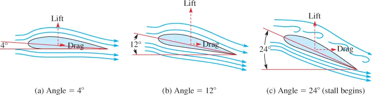
Figure 2 Angle of Attack. As attack angle increases, lift increases until the airfoil begins to stall at a high angle of attack. At this point, turbulence begins, causing the lift to decrease and drag to increase. Stall begins at this point.
Lift-to-Drag Ratio
The lift-to-drag ratio is a ratio of the lift force to the drag force, and it varies across the blade.
The higher the lift-to-drag ratio, the more efficient the turbine blade is at converting wind energy into torque, which produces more electricity from the generator.
Turbine blades have the highest lift-to-drag ratio near the tip of the blade. The blade has more material with very high strength near the hub because of the higher stresses in that region, and less material near the narrow tip. For this reason, lift is increased and drag is reduced near the tip.
Various factors affect drag, including the materials used to construct the blade, wind speed, air density, and air temperature. Even dirt and bugs on the blade affect drag. Drag is also affected by how the blades are oriented.
Stall occurs at very high angles to the wind and the blade no longer has lift. A wind turbine is subjected to the highest and lowest winds that flow at its location.
When high winds occur, the turbine blades increase their speed, and the output of the generator may increase to the point at which the generator becomes overheated and damaged.
Also, high winds may damage the turbine blades and the tower if the generator is allowed to increase its output at an uncontrolled rate.
Turbine Blade Tip Speeds
The tip of the turbine blade travels at the highest speed of any part of the turbine blade when it is rotating. Because of this speed, the tip passes more air as it travels and hence generates more lift.
Tip speed is defined as the speed at the blade tip as it rotates through the air.
Because the tip is rotating at the highest speed, it comes under considerable stress caused by centrifugal force.
Blades are specified for a maximum tip speed and they are tapered to reduce lift at the ends because the faster-moving tip can still generate sufficient lift.
High tip speed is defined as speeds between 65 and 85 m/s, which is about 145 to 190 mph.
High tip speeds are needed to make the turbine blade more efficient. At very high speeds, the turbine blade may receive too much stress, which can cause deterioration due to micro-fracturing.
A turbine blade must be designed to withstand the maximum stress. A specification that is important is the ratio of the tip speed to the wind speed, or the tip speed ratio (TSR).
Tip speed can be determined from the rotational speed, which is ωR where ω is the rotational speed in radians per second and R is the radius of the turbine in meters.
The optimal tip speed ratio depends on the number of blades and is lower when there are more blades.
For three blades, a TSR of 6 to 7 is optimal. If it is less, not all the available energy is captured; if it is more, the blades move into an area of turbulence from the last blade and are not as efficient.
Because the speed of the blade is faster near the tip, the tip speed ratio is only valid at the radius used in the calculation.
To optimize the angle of attack all along the blade, the blade is twisted from root to tip.
Twist
Because of the difference in speed along the blade, the optimum angle for the tip is not the same as the optimum angle of the main part of the blade.
A twist is added along the length of the blade to optimize the amount of energy harvested. Typically, 10° to 20° of twist is included, with the twist at the tip being the highest. This produces a change in the apparent wind direction across the blade. Recall that if the rotational speed is zero, the true wind direction and the apparent wind direction are the same.
Wind Turbine Blade Aerodynamics Review Questions
- What is the lift?
- How is drag different on a wind turbine than on an airplane wing?
- What is the lift-to-drag ratio?
- How do you calculate tip speed?
- What is TSR?
Answers
- It is a force on a blade or wing created by a pressure difference between two surfaces.
- Drag is a friction force that always opposes the motion. On an airplane wing, it is oriented toward the rear; on a wind turbine blade, it is a rotational force that is directed away from the blade motion.
- The ratio of the lift force to the drag force and it varies across the blade
- Tip speed = ωR where ω is the rotational speed in radians per second and Ris the radius of the turbine in meters.
- Tip speed ratio; it is the ratio of the tip speed to the wind speed.
Wind Turbine Blade Aerodynamics Key Takeaways
Understanding wind turbine blade aerodynamics—including lift, drag, angle of attack, tip speed, tip speed ratio (TSR), and blade twist—is essential for designing efficient and durable turbines. These aerodynamic principles directly impact how effectively a turbine can convert wind energy into mechanical power and, ultimately, electricity. Properly optimizing these factors allows for greater energy capture, reduces mechanical stress, minimizes energy losses, and ensures safe operation across varying wind conditions.