In the circuit of Figure 1, we assume that the inductor has negligible resistance. To satisfy Kirchhoff’s voltage law, at every instant the inductive voltage across the coil in Figure 1 must exactly equal the applied voltage. Hence,
\[{{v}_{L}}=e={{E}_{m}}\sin \omega t \]
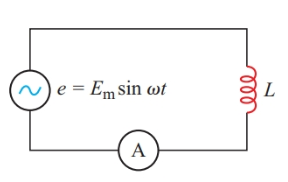
Figure 1 Inductance in an ac circuit
If there is no resistance in the circuit, any voltage drop that appears across the terminals of an inductor must be due to the voltage induced in the coil by a changing current through it. The instantaneous voltage across the inductor in Figure 1 must be:
\[{{v}_{L}}=L\frac{di}{dt}\]
Therefore,
\[L\frac{di}{dt}={{E}_{m}}\sin \omega t\]
And
\[\begin{matrix}\frac{di}{dt}=\frac{{{E}_{m}}}{L}\sin \omega t & {} & \left( 1 \right) \\\end{matrix}\]
Since Kirchhoff’s voltage law requires the voltage across the inductor to be exactly equal to the applied voltage at every instant, we can represent the instantaneous voltage vL across the inductor by the blue sine curve in Figure 2. According to Faraday’s law of electromagnetic induction, the magnitude of this inductive voltage at any instant is directly proportional to the rate of change of current through the coil at that instant.
When the maximum positive voltage appears across the inductor (at the point where $\phi ={}^{\pi }/{}_{2}$ rad), the current must be changing at the greatest positive rate. Since$\phi =\omega t$, the slope of a graph of the current versus phase angle is directly proportional to the rate of change of current with time. In Figure 2, the maximum rate of change is indicated by the steepest slope.
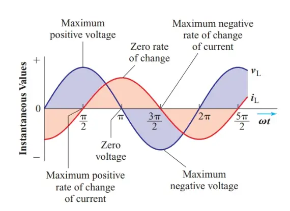
Figure 2 Instantaneous current in an inductor
One quarter-cycle later (when $\phi =\pi $ rad), the instantaneous voltage is momentarily zero, and the current must momentarily stop changing. Regardless of how great the current may be, as long as it is neither rising nor falling, there is no change in the magnetic flux linking the turns of the coil and, hence, no induced voltage. Therefore, the slope of the instantaneous current curve must be horizontal at this instant.
Between ${}^{\pi }/{}_{2}$ rad and $\pi $ rad, the voltage across the inductor has to decrease along a sine curve, and thus the rate of change of current has to decrease in the same manner. Another quarter-cycle later (when $\phi ={}^{3\pi }/{}_{2}$ rad), the instantaneous inductive voltage reaches its most negative value, and therefore the instantaneous current must be changing at its maximum negative rate.
The instantaneous current through the inductor must have the sine-wave shape shown by the red curve in Figure 2 in order to induce the sinewave voltage that appears across the inductor. But the instantaneous current sine wave reaches its positive peak a quarter-cycle (${}^{\pi }/{}_{2}$ radians) after the instantaneous voltage across the inductor reaches its maximum. The zero and minimum values of the current also occur a quarter-cycle after the corresponding points in the voltage wave. Therefore,
For a sine-wave voltage drop to appear across an ideal inductor, the current through it must be a sine wave that lags behind the inductive voltage drop by ${}^{\pi }/{}_{2}$ radians.
Therefore, the instantaneous current in the circuit of Figure 1 is
\[\begin{matrix}{{i}_{L}}={{\operatorname{I}}_{m}}\sin \left( \omega t-\frac{\pi }{2} \right) & {} & \left( 2 \right) \\\end{matrix}\]
Where the phase angle ωt-π/2 is measured in radians.
The following process shows how to derive the above equation by using integral calculus.
When an ideal inductor is connected across a sine-wave voltage source, the instantaneous voltage drop across the inductance must equal the instantaneous applied voltage:
\[L\frac{di}{dt}={{E}_{m}}\sin \omega t\]
Therefore,
\[\frac{di}{dt}=\frac{{{E}_{m}}}{L}\sin \omega t\]
Indefinite integration of this equation gives,
\[i=\frac{{{E}_{m}}}{L}\int{\sin \omega t\text{ dt}}\]
\[=\frac{{{E}_{m}}}{\omega L}\left( -\cos \omega +C \right)\]
Except during transients caused by opening or closing a switch in the circuit, the constant of integration, C, is zero. Since $-\cos \theta =\sin \left( \theta -{}^{\pi }/{}_{2} \right)$ ,
\[\begin{matrix}{{i}_{L}}=\frac{{{E}_{m}}}{\omega L}\sin \left( \omega t-\frac{\pi }{2} \right) & {} & \left( 3 \right) \\\end{matrix}\]
- You May Also Read: Instantaneous Current in a Capacitor