This guide covers armature reaction in DC Machine (Generator and Motor) and how to correct it using Brush Shift, Compensating Winding, and Interpoles.
An armature, when rotating in its magnetic field, can have varying values of current flowing in its coils. The current can vary from zero at no load to the designed maximum, the actual value depending on the size of the machine. The armature, in carrying the current, sets up a magnetic field of its own. This field combines with the main field, producing a resultant field, and the process is called armature reaction.
The resultant field is twisted in either the direction of rotation or against it, depending on whether the machine is being used as a generator or a motor.
Main Field Distortion
A generator that has no load on the armature has no current flowing in the armature conductors and consequently there is only one magnetic field, that intentionally provided for the armature conductors to cut and generate a voltage. This is shown in Figure 1(a), with the magnetic field leaving the North Pole, crossing the air gap to the armature core, and eventually entering the South Pole on the opposite side.
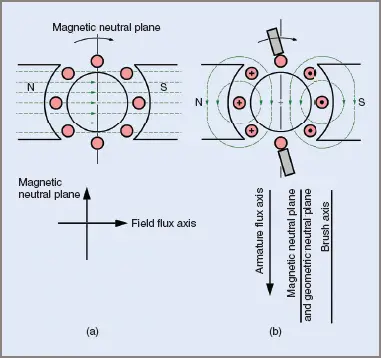
Figure 1 Magnetic fields in a DC armature
Its direction is parallel to the center line or axis through the field pole. At 90°E to the polar axis is the geometrical neutral position. Under no-load conditions the geometrical neutral plane is also accepted as the magnetic neutral position or plane.
Unlike the geometric neutral, which is in a fixed position, the magnetic neutral position can be varied by a shift in the magnetic field. The relative positions of the planes are shown in Figure 1(b).
Figure 1(b) also shows the field created in a two-pole armature by load current flowing through the armature conductors. This field is set up at right angles to the main field and parallel to the magnetic neutral position. Taking each field in isolation, the relative directions are in either the horizontal or the vertical planes.
In a practical case the armature field can only be present if the main field is also present, so there are actually at least two magnetic fields present when the machine is on load. The end result is a combination of these fields into one resultant field, whose direction will depend on the relative strengths of each field.
The shift in the main field axis is illustrated in Figure 2(a). It has shifted ahead in the direction of rotation and has become more concentrated at the trailing pole tips, with a consequent weakening of the field strength at the leading pole tips.
Figure 2(c) shows the vector approach for determining a direction of the resultant field, while Figure 2(b) shows the angle of shift for the magnetic neutral plane.
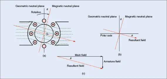
Figure 2 Field shift due to armature reaction in a DC generator
Figure 3 shows the shift in the main field for a DC motor. For the same direction of rotation, the shift is in the opposite direction to that of the generator (i.e. against the rotation of the armature).
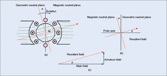
Figure 3 Field shift due to armature reaction in a DC motor
Whether the machine is being operated as a generator or a motor, the result of loading the machine is to shift the field flux to a new position. The amount of shift depends on the size of the load applied.
The brushes are placed nominally in the magnetic neutral plane at full load to obtain the best commutation performance. While they are not in the magnetic neutral plane at light loads, less current is flowing and the sparking is less.
At no load, which actually means just the load caused by the rotational losses, less current is flowing and the sparking at the brushes is less if the brushes are misaligned. Therefore the brushes are normally set for full load field distortion. This is fine for constant load machines and those with only a small variation in load.
Correction of Armature Reaction
DC machines are often used for their inherent ability to run over a wide range of speeds and loads. Therefore other methods of controlling brush arcing are often necessary. For reliability, a DC machine must have good commutation to extend the working life of both the commutator and the brushes.
Brush Shift
The simplest method is to shift the brushes into the new position of the magnetic neutral plane each time the load is altered. It is a satisfactory method for loads that are relatively constant or change only occasionally. Where loads are subject to sudden or rapid change, this method is unsatisfactory.
Brush shifting is also employed on generators (or motors) that change direction, as was the case with old railway carriage generators that were driven in whichever direction the carriage went.
Compensating Windings
Correctly designed and installed compensating windings are arguably the most successful method of minimizing armature reaction; but alas, the most expensive. Compensating windings are coils wound onto the main field poles (see Figure 4(a)).
Compensating windings are connected in series with the armature so that the load current in the coils is always equal to the armature current and therefore produce a magnetic field opposing the field set up by the armature.
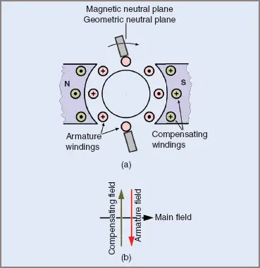
Figure 4 Compensating windings
Effectively, of the three magnetic fields produced in the machine, two cancel each other out, leaving the third (the main field) unaffected. The magnetic neutral plane remains undisturbed and the brushes can remain in it, irrespective of any load applied to the machine. Figure 4(b) shows the vectors for the magnetic forces.
Interpoles
Interpoles are smaller than the main field poles, placed between the main field poles and are connected in series with the armature. The number of turns multiplied by the armature current gives the necessary ampere-turns to produce a magnetic field equal in strength to that of the armature cross-field.
Interpoles are shown in Figure 5(a) and illustrate the difference in size compared with the main field poles.
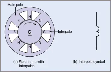
Figure 5 Location of interpoles
To cancel out the effects of armature reaction, the interpoles must be connected to give a specific polarity with respect to the main poles on either side. The connection is unaffected by the direction of rotation, as long as the interpoles and armature are treated as one, that is, direction reversal is achieved by changing the polarity of either the fields or the armature/interpole group.
Once the correct connection has been found, that one connection will remain constant no matter what use the machine is put to, motor or generator.
Figure 6 shows the polarities of the interpoles for a motor or generator being driven clockwise.
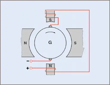
Figure 6 Interpole connections
Interpoles are very effective for minimizing the effects of armature reaction, being cheaper than compensating windings but not as effective. For rapidly fluctuating loads, compensating windings are far more effective than interpoles, but in very large machines both methods may be employed. This is shown in Figure 7.
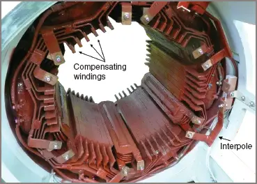
Figure 7 Part of a large DC motor showing the compensating windings and interpoles