The article provides an overview of brushless DC motor, focusing on their working principle, construction, and electronic commutation process. It also highlights the advantages, limitations, and various design configurations of these motors used in modern applications.
A DC machine actually has an AC current in the armature that is rectified by the commutator and brushes. Brushes eventually wear out, requiring maintenance, and they produce carbon dust and possibly arcing while operating. Nevertheless, the characteristics of DC machines are often desirable. With the advances in power electronics, it became possible to have a “brushless DC motor.” This term does not, however, describe a unique motor design, and in fact, the motor is DC in name only.
This article will consider a common class of brushless DC motors that use electronic commutation. Recall the synchronous motor with a three-phase winding (the armature) on the stator and a DC winding (or a permanent magnet) on the rotor. Under normal operation, a balanced set of AC voltages are applied to the stator windings, producing a rotating magnetic field that “pulls the rotor” along with it.
Figure 1 shows a permanent-magnet synchronous motor with salient poles on the stator. Instead of applying a balanced set of voltages to the stator, the output of an inverter is applied to the windings. By exciting the poles in sequence, the permanent magnet is made to follow the rotating magnetic field.
The brushless DC motor has several advantages over a regular DC motor:
- Little or no maintenance
- Longer operating life
- No arcing, so there is no explosion hazard or RFI
- No carbon particles floating around
- Can be sealed to operate in fluids
- More efficient than conventional DC motors
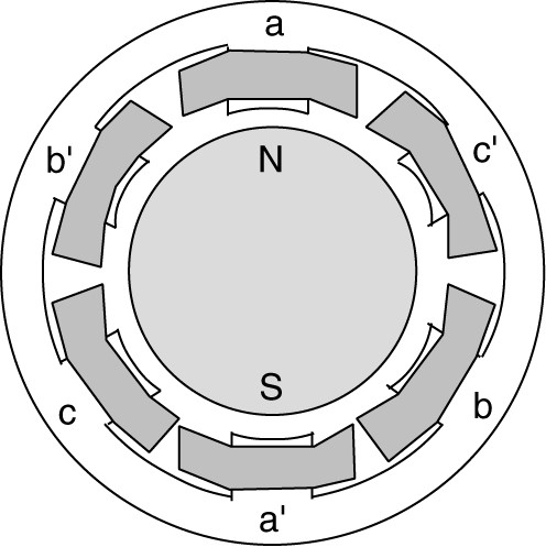
Figure 1: Cross section of a brushless DC motor.
There are also disadvantages, of course:
- Larger total package due to electronics
- Higher initial cost
Brushless DC Motor Operation
Figure 2 shows the operation of the brushless DC motor. In Figure 2 (a), the north pole of the rotor field is located between the a and b’ stator poles. If a voltage is applied to the a and a’ coils so that current flows as shown, the magnetic flux of the stator coils will be straight up, producing a south pole at the 12 o’clock position (the top of the motor). Thus, there will be a magnetic force between the stator field and the rotor, causing a torque that rotates the rotor clockwise toward the a pole.

Figure 2: Operation of the brushless DC motor.
In Figure 2(b), the north pole of the rotor has moved to 12 o’clock. As the rotor arrives there, voltage is applied to the c-c’ coils to produce current as shown. This advances the stator south pole to the 1 o’clock position. The rotor field will follow the stator field due to the magnetic attraction. When the rotor north pole arrives at 1 o’clock, the current in coils a-a’ is disconnected, leaving the only current in coil c. This moves the stator south pole to 2 o’clock, causing further motion of the rotor. The process continues through all 12 panels, alternately connecting and disconnecting coils to move the stator flux around the air gap.
Note that the current in the coils is alternating. Panel (g), for example, is the exact opposite of panel (a), because the current in coils a-a’ has reversed. The commutation process is done electronically with SCRs or switching transistors.
Figure 3 shows the ideal voltages applied to the coils. Of course, there is inductance in the coils so the currents can’t be turned on and off instantaneously. Thus, the currents are more trapezoidal than rectangular.
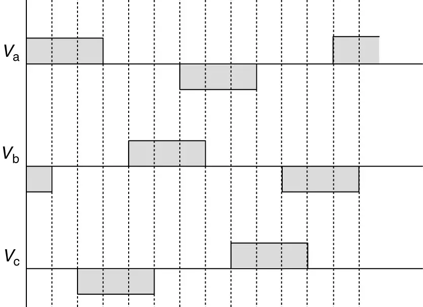
Figure 3: Phase voltages in the brushless DC motor of Figure 2.
At this point, you should be wondering, “How do we know when to switch the currents in the coils?”
Clearly, to make the motor operate as shown in Figure 2, there must be some way of knowing where the rotor is. Figure 4 shows how this could be accomplished. Mounted on the motor shaft is a cam that rotates over optic sensors. By proper design of the cam and location of the sensors, it is possible to determine where the poles of the rotor are located. An alternative method is to use Hall Effect sensors, which “pick up” the presence of the rotating rotor field.
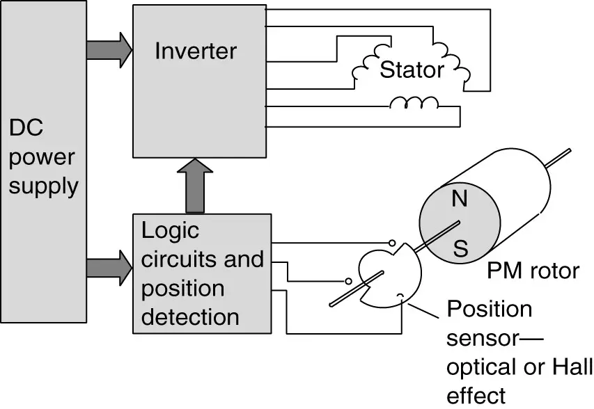
Figure 4: Block diagram of brushless DC motor system.
The speed of the motor can be controlled by changing the magnitude of the voltage that is applied to the stator coils. Increasing the voltage increases the speed of the motor, much like it does in a DC motor.
Figure 5 shows the torque-speed characteristic for a brushless DC motor. By reversing the process shown in Figure 2, it is possible to run the motor in the opposite direction, shown in the third quadrant of the graph in Figure 5.
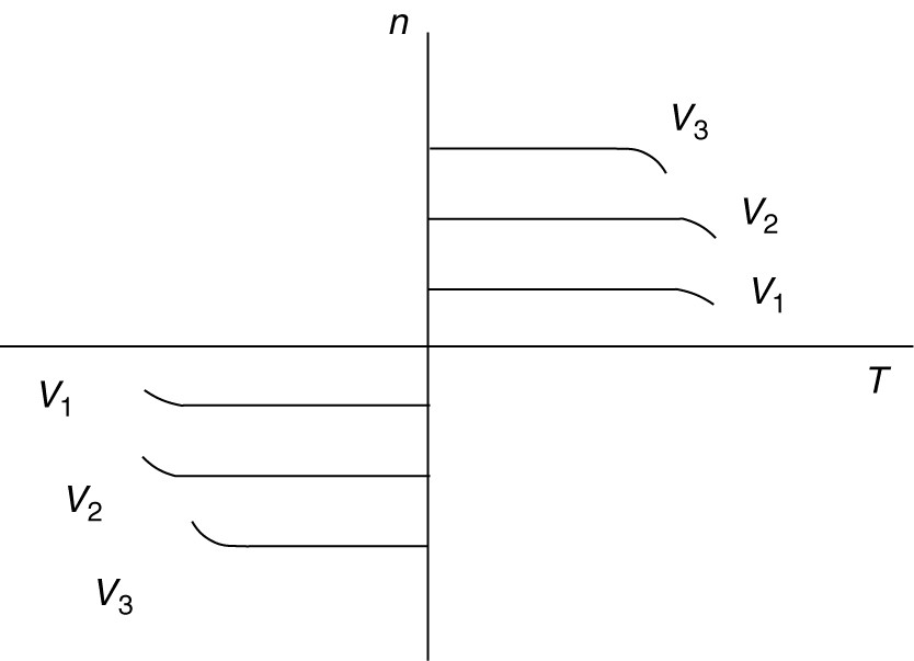
Figure 5: Torque-speed characteristic of a brushless DC motor.
The typical configuration of brushless DC motors is shown in Figures 1 and 2, but they are also built in other configurations.
Disk drives, in particular, require so-called pancake motors, which are very thin. To accomplish that, the rotor is placed outside the stator. This creates a higher moment of inertia, which helps keep the machine speed constant.
Figure 6 shows two brushless DC motors of different designs. Notable on both motors is the electronic circuit board, which is required to operate the motor. The motor on the right has a salient-pole stator, and the permanent magnet material is mounted on the inside of the outer rim of the rotor. The motor on the left has flat, air-core coils on the stator, and the permanent magnets are mounted inside the surface of the rotor.
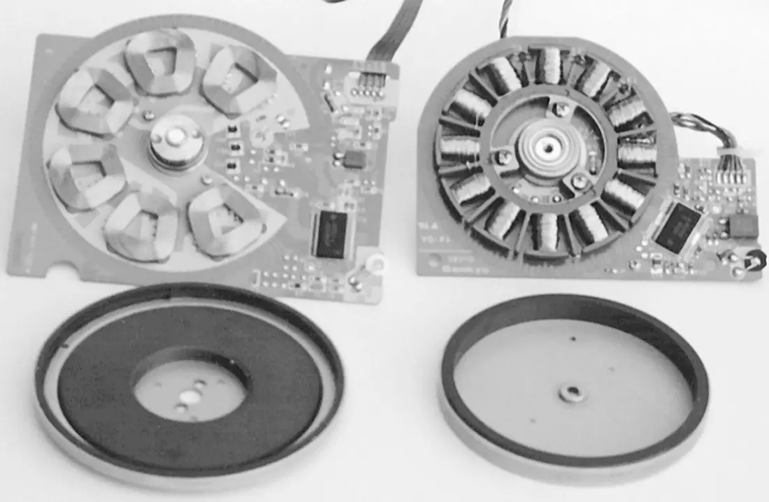
Figure 6: Two pancakes brushless DC motors.
Brushless DC Motor Key Takeaways
Understanding the working principle, construction, and electronic commutation of brushless DC motors is essential due to their significant role in modern applications. Their high efficiency, low maintenance, and ability to operate in sealed or hazardous environments make them ideal for a wide range of industries—from computer cooling fans and electric vehicles to aerospace systems and medical equipment. The elimination of mechanical commutators not only enhances durability and reliability but also allows for more precise control through electronic circuits. These advantages, combined with flexible design options like pancake configurations, underscore why brushless DC motors are increasingly preferred in applications demanding compactness, precision, and long-term performance.