This guide covers DC Servo Motor and Stepper Motor Working Principle, Block Diagrams, and their Applications. Further, it also covers Brushless DC Motor Operating Principle and its Applications.
DC Servo Motor Working
A DC servo motor is usually defined as any motor that can be remotely controlled by providing negative feedback. It is essential that the response characteristics be identical in both directions of rotation. It must be able to stop, start, change direction, run at constant speed or take up accurately any desired position throughout 360°.
To do this there are two distinct types of DC servo motors. One is a rotating machine free to rotate in either direction, the other a semi-stationary machine that only rotates to take up a particular position or angle when required by the system. In this there are also two distinct types. One moves in discrete steps of fixed angles (stepper motor) while the other is able to take up any angle of rotation and maintain that angle (positional control).
The advantages of DC servo motors are:
| 1. | Higher output torque for the same-sized motor |
| 2. | Control with smaller input currents |
| 3. | Easy to stabilize |
| 4. | High efficiency. |
DC Servo Motors and Servomechanisms
Servomechanisms are a class of control systems that form a control loop. The controller sets a condition, such as a position or speed, which is relayed to a servo motor. The DC servo motor operates according to the controller.
The operation of the servo motor is measured by some appropriate device and the reading relayed back to the controller. The controller compares the setting to the measured result and calculates the error. The controller then adjusts the signal to the servo motor to cancel out any error.
A block diagram of a typical DC servo system is shown in Figure 1.
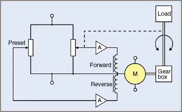
Figure 1 DC Servo motor block diagram
DC Servo Motor Applications
The study of such systems is known as ‘process and control’. Electrical workers working in manufacturing industries and in production factories often work on process and control systems, however, instrument fitters often specialize in these areas.
Stepper Motor Working
A stepper motor can rotate in either direction, one step at a time, back and forth, or step after step as pulses are applied by the controller. Stepper motors do not rotate automatically as other motors do.
The stepper motor will stand still if a continuous DC current is applied. Therefore they do not fit neatly into either DC or AC motor categories, as rotation is a result of pulses of DC current, often at differing polarities that could be interpreted as alternating square wave current, i.e. AC.
The name ‘stepper motor’ is usually given to a motor that can rotate in fixed increments of rotation, say, in steps of 30° or 15°, or even as small as 1 ° increments.
Figure 2 shows an elementary stepper motor with three windings and a two-pole permanent magnet. Table 1 shows the magnetic polarities available to produce the steps in increments of 30°, giving a total of twelve different positions.
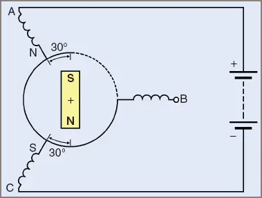
Figure 2 Incremental control with a stepper motor
Table 1 Polarities for Stepping Motor in Figure 2
| Windings | |||
| Position | A | B | C |
| 1 | − | 0 | + |
| 2 | − | − | + |
| 3 | 0 | − | + |
| 4 | + | − | + |
| 5 | + | − | 0 |
| 6 | + | − | − |
| 7 | + | 0 | − |
| 8 | + | + | − |
| 9 | 0 | + | − |
| 10 | − | + | − |
| 11 | − | + | 0 |
| 12 | − | + | + |
The stepper motor can skip over increments. For example, it can be made to have six steps instead of 12, and can sometimes move to any step according to any given electrical connection.
When moving the magnet from one position to another at fast stepping rates, inertia often causes the magnet to overshoot the correct position. It then has to rotate backwards in the opposite direction, hunting for the correct position. Without some damping effect this can cause undesired oscillation about any desired point. Some inherent natural damping is created by the generation of eddy currents, but additional damping might be required.
Due to the permanent magnet, stepper-motor rotors will stop in a position of best magnetic flux flow, aligned to a set of poles. This can be felt when you try to rotate a stepper-motor rotor as distinct steps in the rotation, even without power applied.
Stepper Motor Applications
Stepper motors are commonly used in computer printing machines, machine tool systems such as numerically controlled machines and remote positioning systems such as space applications.
Four-Phase Stepper Motors
When a greater number of steps per revolution is required a four-phase stepper motor is used. The four-phase motor uses a toothed rotor and toothed poles with four coils as four separate poles, though there may be pairs of poles in larger motors.
Figure 3 shows a simplified motor with four poles and 36 teeth in the rotor, providing 144 steps in total. Each pole face has teeth to match the teeth in the rotor except they are ¼ of a tooth advanced with respect to the previous pole face. If the poles are energized one at a time in the order A – B – C – D etc. the rotor will turn clockwise 2.5° in each step. (A motor with 90 teeth could provide 360 steps each of 1°.)
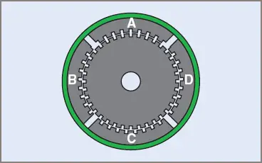
Figure 3 A four-phase stepper motor
The motor may be geared to effect a greater number of steps on an output shaft and the position of the output taken from a rotary encoder or counted from the number of steps the motor has taken from its parked position.
Brushless DC Motor Working
A computer disk drive assembly has two motors. One is a stepper motor. Its function is to shift the reading head across the magnetic tracks on the disk. It usually has more poles than described in the above section.
The second motor in the assembly is a hybrid type of brushless DC motor. Its function is to drive the disk at a constant speed of (usually) 300 revolutions per minute. Because the motor has no commutator, the coils have to be electronically switched. See Figure 4 for a simplified circuit.
The stationary central section of the assembly often comprises two sets of iron-cored poles in series, although some models use three sets of windings.
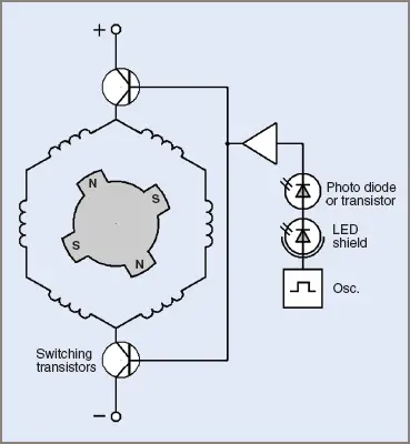
Figure 4 Principle of operation of a brushless DC motor
A brushless DC motor for a computer fan is shown in Figure 5(a). The coils and rotor of the same motor are shown in Figure 5 (b) and (c).
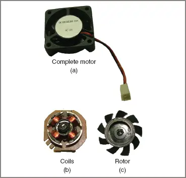
Figure 5 Brushless DC motor used as a computer fan
Speed and position sensing is provided by a central printed circuit giving control over the transistor-switched circuitry supplying power to the main windings. Motor rotation and speed is monitored by sensors, often comprising small light-emitting diodes that may be switched on and off rapidly.
Other methods are the use of magnetic sensors or Hall-effect semi-conductors. For each method, the primary function is to control the speed of the motor as accurately as possible and to sense the position of the rotating magnet in relation to the fixed wound poles for correct switching or commutation of the coils.
Minor variations in speed are further compensated for by a phase-locked loop system incorporated in the drive circuitry for the stepper motor.
The outer rotating part is a circular ring of magnets that may match the number of fixed wound poles. The outer ring, because of its greater weight, also tends to act as a flywheel to stabilize against minor speed fluctuations (see Figure 5(c)).
It is not recommended that dismantling one of these motors be undertaken lightly. For disk drives in particular, the positions of both motors in the drive have to be synchronized with each other and with the standards for disk drives. A lack of synchronism with the standards usually means the drive is useless for any other machine and disks cannot be interchanged with those used in other machines.
DC Servo & Stepper Motor Key Takeaways
Understanding the working principles and applications of DC servo motors, stepper motors, and brushless DC motors is essential for anyone involved in modern automation, robotics, and precision control systems. These motors play a vital role in numerous industries due to their ability to provide precise positioning, controlled speed, and efficient operation. DC servo motors are key to feedback-based systems where accuracy and responsiveness are critical, such as in CNC machines and industrial automation. Stepper motors are ideal for applications requiring discrete motion control, like 3D printers and satellite positioning systems. Brushless DC motors, known for their durability and low maintenance, are indispensable in computer hardware, drones, and electric vehicles.