The article provides an overview of DC machine construction and operation, including how commutation enables the conversion between AC and DC within motors and generators. It also discusses the components and functionality of both permanent-magnet and wound-field DC machines.
Figure 1 shows elementary permanent- magnet machine. It is very similar to the AC machine; however, instead of a pair of slip rings to connect to the ends of the coil, there is a single split ring. Each end of the coil is connected to one-half of the ring, and two brushes ride on the split ring.
If the coil is rotated between the magnets, an AC voltage will be induced in the coil, or, for motor operation, an AC voltage must be applied to the coil to make it rotate continuously.
To operate the machine from a DC source, it is necessary to convert the DC source to AC in the coil for motor operation or to convert the AC from the coil to DC for generator operation.
The split ring in Figure 1 is called a commutator and has the function of converting between AC in the armature and DC at the machine terminals. The action of changing the connections between the brushes and the coil sides is called commutation.
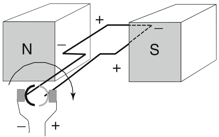
Figure 1 An elementary DC machine.
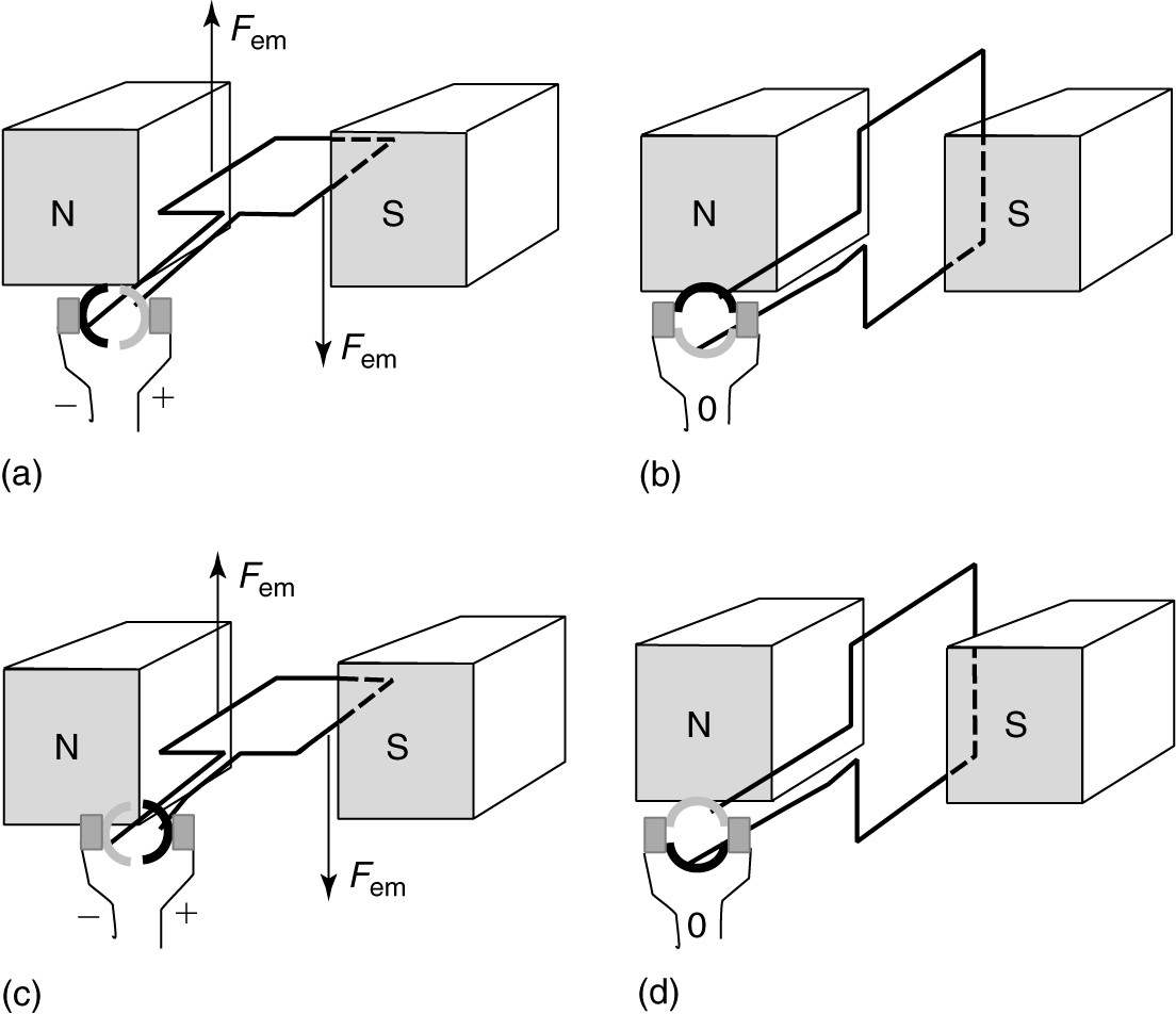
Figure 2 A simple DC motor.
DC Machine as a Motor Operation
Figure 2 shows several views of the simple DC machine operating as a motor. In the first view, Figure 2(a), the dark-shaded half of the split ring is connected to the coil side under the North Pole, and the light-shaded half is connected to the coil side under the South Pole.
With the voltage applied as shown, current flows into the right side of the coil and out of the left side. Since the current is flowing in the presence of a magnetic field, there will be a force on the conductors. That force can be determined by either the left-hand rule or by flux bunching.

Figure 3 Flux bunching in the simple DC motor.
Figure 3 shows a cross-sectional view of the simple DC motor. The flux due to the permanent magnets goes from the North Pole to the South Pole, as shown by the straight arrows. The flux due to the current will surround the conductors, as shown by the dotted circles. Since the current is into the page on the right side of the coil, the conductor’s flux will be in the clockwise direction by the South Pole.
Notice that the conductor’s flux adds to the permanent magnet flux above the right conductor and subtracts below it. Thus, there will be a downward force on the right side of the coil, as shown in Figure 2(a).
On the left side of the coil, the current is out of the page, causing counterclockwise flux that results in more flux below the conductor. This means there will be an upward force on the left side of the coil. The forces on the two sides of the coil will cause the coil to rotate.
Eventually, the coil reaches the position shown in Figure 2(b). Here, the brushes are shorting out the coil as they move from one side of the commutator to the other. There is no current in the coil (actually the current decays to zero due to the inductance of the coil), and there is no force on the conductors. This is called the magnetically neutral position. Assuming the coil has sufficient momentum, it will continue to rotate past the neutral position.
In Figure 2(c), the positions of the commutator segments and the coil sides have reversed from part (a). The dark segment is now connected to the positive terminal, and current flows into the dark segment instead of out. Thus, the commutator has inverted the DC source to provide AC to the coil.
The conditions in part (c) are exactly the same as in part (a) so far as the directions of the currents and fluxes, so the forces remain in the same direction. Figure 2(d) shows the commutation back to the original state.
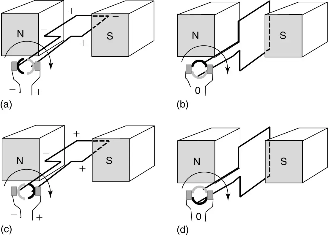
Figure 4 A simple permanent-magnet DC generator.
DC Machine as a Generator Operation
Figure 4 shows four views of the simple DC machine operating as a generator. In Figure 4(a), both coil sides are cutting flux at a maximum rate, as their velocity is perpendicular to the flux. By the right-hand generator rule, the polarity of the voltage is as shown.
As the coil rotates to the vertical position, shown in Figure 4(b), the coil sides are no longer cutting flux, and the brushes are commutating from one side of the split ring to the other. The brushes temporarily short out the coil, but there is no voltage induced since the coil velocity is parallel to the flux in this position. As the coil continues to turn, a voltage is again induced, but because the coil side under the North Pole is still connected to the left brush, the voltage polarity at the terminals remains unchanged, as shown in Figure 4(c).
Finally, Figure 4(d) shows the coil returns to the neutral position again. This machine generates AC voltage in the coil but produces a DC voltage at the machine terminals due to the rectifying action of the commutator.
DC Machine Construction
The simple DC machine described in the previous section used a permanent magnet to establish the magnetic field. Although some DC machines have a permanent-magnet field, the overwhelming majority use coils to create the field.
Figure 5 is a sketch of the construction of a DC machine. The field coils are placed behind the pole-faces, as shown, and the rotor contains the armature coils, although only one coil is shown in Figure 4.
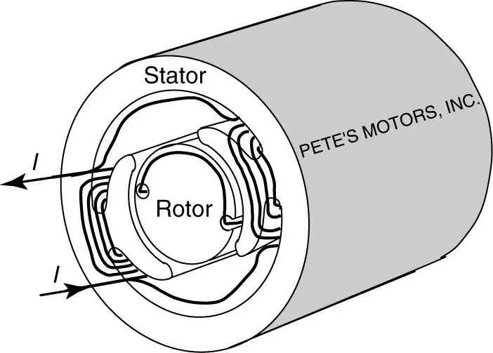
Figure 5 DC machine construction.
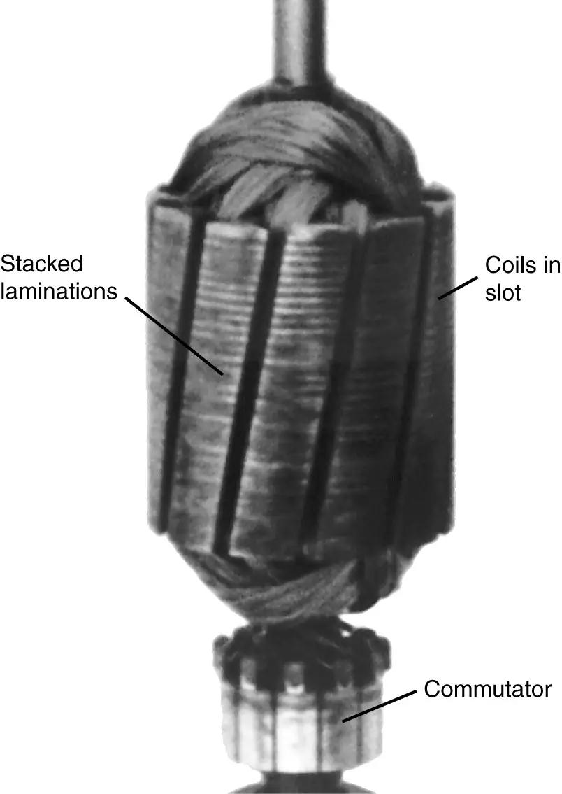
Figure 6 Photograph of a DC armature.
Rotor
Figure 6 is a close-up view of a DC machine armature. To make more effective use of the space in the machine, numerous coils are placed on the rotor in slots, as shown. The coils are connected to the commutator at the bottom of the rotor.
Because the armature windings carry AC current, the rotor is built of a stack of laminations. Figure 7 shows a typical rotor lamination from a DC machine. For small machines, the windings would be wound directly into the slots of the rotor using numerically controlled machines. For large machines, the windings would be wound separately and then placed into the slots of the rotor.
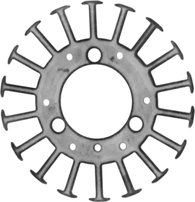
Figure 7 Rotor (armature) lamination of a DC machine.
Stator
The stator of the DC machine contains the field winding. Since the stator only sees DC flux, it can be built out of solid steel; however, stators for small DC machines are usually built from laminations to reduce cost.
Figure 8 shows a lamination for a two-pole wound-field DC machine. The ear-shaped appendages hanging out in the center are the pole- faces that will be directly opposite the rotor. The field coils are wound and then placed behind the pole-faces. On large DC machines, the pole-face is typically bolted on to allow easier installation and replacement of the field coil.
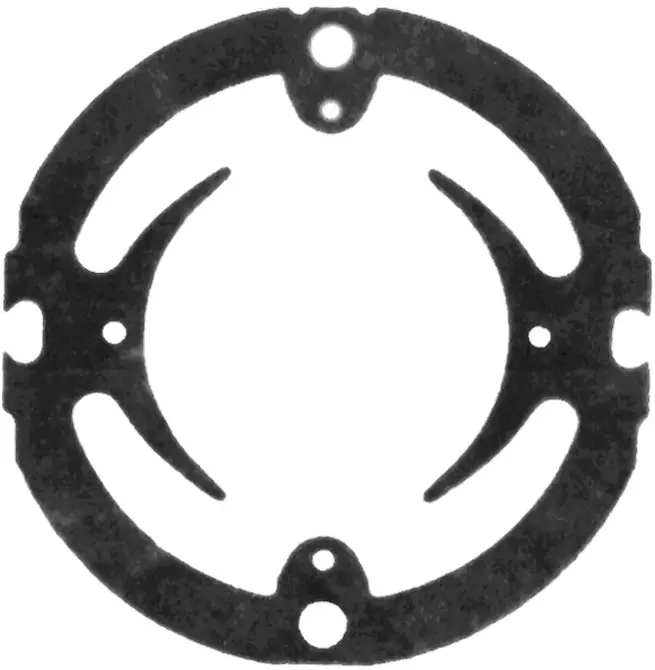
Figure 8 Stator (field) lamination of a DC machine.
Figure 9 shows a cutaway view of a wound- field DC machine. The field coil at the front of the machine has been cut and the ends of the coil can be seen surrounding the pole. The commutator and one brush are seen on the left side of the ma chine.
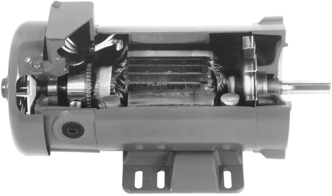
Figure 9 Wound-field DC machine.
Permanent-magnet DC machines are also available, primarily in smaller sizes. Figure 10 shows a cutaway view of a permanent-magnet- field DC motor.
The permanent-magnet field has a couple of advantages over the wound field. First, the machine is somewhat more compact, as the permanent magnet is thinner than the coil and pole-face assembly. Second, the machine is more efficient because there are no field losses.
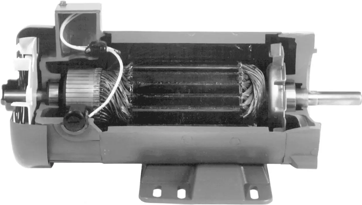
Figure 10 Permanent-magnet-field DC machine.
The machines shown here can be operated as motors or as generators. The operation is basically the same as the foregoing description for the simple DC machines.
For motor operation, a DC voltage is applied to the armature terminals. The commutator inverts the DC to provide an AC voltage to the armature windings. The difference, of course, between the machines shown in Figures 9 and 10 and the simple DC machine is that the real machines have multiple coils on the armature. Thus, the total force on the rotor is the sum of the forces on all of the coils, and when commutation occurs there are still other coils with forces on them.
Similarly, for generator operation, the armature coils can be connected in various series and parallel combinations, depending upon the machine design. The total generated voltage is the sum of the voltages in the coils that are in series, and during commutation, there is still voltage being generated.
DC Machine Construction and Operation Key Takeaways
Understanding the construction and operation of DC machines is essential because these machines play a critical role in a wide range of practical applications. The ability to convert between AC and DC using commutation allows DC motors and generators to function efficiently in systems that require stable and controlled power output. Their precise torque control, ease of speed regulation, and straightforward design make them ideal for applications such as electric vehicles, industrial automation, railway traction, and backup power systems. Additionally, the use of permanent-magnet and wound-field configurations allows engineers to choose machines optimized for size, efficiency, and performance, depending on the application.