The article discusses the functionality and advantages of Pulse Width Modulated (PWM) inverters, focusing on their ability to control voltage and frequency using intelligent switching. It also highlights the evolution of PWM technology, including the impact of high-frequency switching and the introduction of IGBT devices on motor performance and insulation requirements.
The Pulse Width Modulated (PWM) inverter offers the ability to change both the magnitude of the voltage and the frequency using a fixed DC voltage as the input. This means a diode rectifier can be used as the front end of the drive, which appears as a constant power factor load to the source.
The PWM requires an intelligent controller, usually a microprocessor, to control the switching. The basic idea is to deliver a series of constant-amplitude, variable-width pulses of voltage to the load to simulate a sinusoidal voltage of the desired frequency. The inductance of the motor keeps the current flowing between the pulses, resulting in an almost sinusoidal current.
There are a variety of control schemes for PWM inverters. Figure 1 shows the principles of sinusoidal modulation, which uses a reference signal and a modulation signal. The reference signal is the desired sinusoidal voltage of the appropriate frequency. The reference signal is a triangular waveform operating at a carrier frequency.
Figure 1 shows the modulation signal (dashed lines) and two reference sinusoidal signals. To determine the switching of the inverter, the reference signal is compared to the modulation signal. When the reference signal is higher than the modulation signal, the inverter switch is turned on to deliver a voltage pulse to the load.
The lower portion of Figure 1 shows the PWM output for the sine wave with full-scale amplitude in the top portion of the figure. Looking at the reduced amplitude sine wave, it should be evident that the pulses will be narrower, reducing the rms of the voltage delivered to the load.
The advantage of PWM switching is a reduction of low-order harmonics, which provides smoother operation of the motor, especially at low speeds.
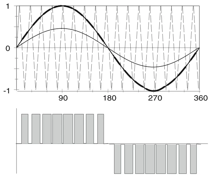
Figure 1: Sinusoidal pulse-width-modulation.
Early PWM inverters were limited to a few kHz for switching, which caused audible noise. The commercialization of the IGBT allowed drive manufacturers to increase the carrier frequency to the 20 kHz regime, well above the capability of the human ear.
The higher carrier frequency also results in smaller magnitudes for the low-order harmonics, at the expense of increased switching losses in the inverter, which means lower efficiency.
The carrier frequency is adjusted to maintain an integer ratio between the carrier frequency and the frequency of the reference signal.
With the introduction of PWM-IGBT inverters in the early 1990s, motor failures due to insulation breakdown suddenly began increasing. The IGBT is capable of delivering voltage pulses with very fast rise times (dV/dt). The voltage pulses are also not square, as shown in Figure 1; rather, they have an overshoot, which can be significantly increased by lengthy feeder cables from the drive to the motor. If the overshoot is severe enough, it can cause breakdown of the insulation in the motor. As a result of the early motor failures, motor manufacturers began producing motors designed for inverter duty.
Pulse Width Modulated (PWM) Inverter Key Takeaways
PWM inverters play a vital role in modern power electronics due to their precise control over voltage and frequency, making them essential for efficient motor drives and variable-speed applications. Their ability to reduce harmonics and improve performance at low speeds, combined with advancements like IGBT technology, has enabled their widespread use in industrial automation, electric vehicles, and energy-efficient systems, highlighting their importance in today’s evolving technological landscape.