The article provides an overview of amplitude and frequency modulation, explaining how each technique modifies a carrier wave to transmit audio signals. It also covers related concepts such as sidebands, modulation percentage, power calculations, bandwidth requirements, and the modulation index.
Modulation is a process in which an audio wave is combined or superimposed on a carrier wave.
Amplitude Modulation (AM)
Assume a radio transmitter is operating on a frequency of 1000 kHz. A musical tone of 1000 Hz is to be used for modulation. Refer to Figure 1. Using a modulation circuit, the amplitude of the carrier wave is made to vary at the audio signal rate.
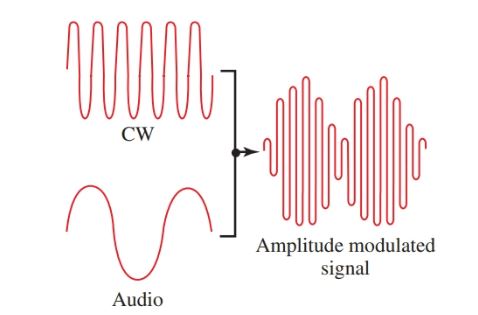
Figure 1. A CW wave, an audio wave, and the resulting amplitude modulated wave.
Let’s look at this process another way. Mixing a 1000 Hz wave with a 1000 kHz wave produces a sum wave and a difference wave, which are also in the radio frequency range. These two waves will be 1001 kHz and 999 kHz. They are known as sideband frequencies. The upper sideband is the higher number and the lower sideband is the lower number, Figure 2.
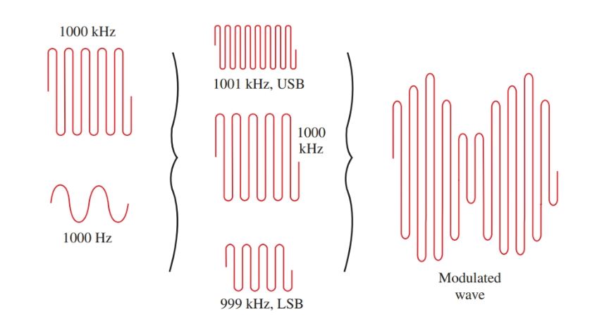
Figure 2. Wave mixing showing the formation of sidebands and modulation envelope.
The sum of the carrier wave and its sidebands is an amplitude modulated wave. The audio tone is present in both sidebands, as either sideband results from modulating a 1000 kHz signal with a 1000 Hz tone.
The location of the waves on a frequency base is shown in Figure 3. If a 2000 Hz tone was used for modulation, then sidebands would appear at 998 kHz and 1002 kHz. In order to transmit a 5000 Hz tone of a violin using AM, sidebands of 995 kHz and 1005 kHz would be required. The frequency bandwidth to transmit the 5000 Hz musical tone will be 10 kHz.
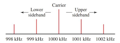
Figure 3. Carrier and sideband locations for modulation tone of 1 kHz and 2 kHz.
There is not enough space in the spectrum for all broadcasters to transmit. And, if all broadcasts contained the same message or operated on the same frequency, the effect would be confusing. Therefore, the broadcast band for AM radio extends from 535 kHz to 1605 kHz. It is divided into 106 channels, each 10 kHz wide.
Each radio station in a geographic area is licensed to operate at a frequency in one of these 106 channels. The channels are spaced far enough from each other to prevent interference.
In order to improve the fidelity and quality of music within these limitations, a vestigial sideband filter is used.
A vestigial sideband filter removes a large portion of one sideband. Recall that both sidebands contain the same information. This way, frequencies higher than 5 kHz can be used for modulation, and the fidelity is improved.
Modulation Patterns
A radio transmitter is not permitted by law to exceed 100 percent modulation. This means that the modulation signal cannot cause the carrier signal to vary over 100 percent of its unmodulated value. Look at the patterns in Figure 4. Notice the amplitude of the modulated waves.
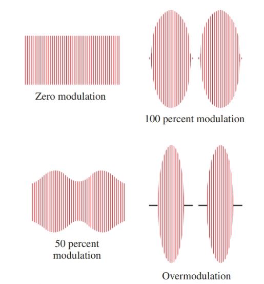
Figure 4. Patterns for 0, 100, and 50 percent of modulation and for over-modulation.
The 100 percent modulation wave variation is from zero to two times the peak value of the carrier wave.
Over-modulation is caused when modulation increases the carrier wave to over two times its peak value.
At negative peaks, the waves cancel each other and leave a straight line of zero value. Over-modulation causes distortion and interference called splatter.
Percent of modulation can be computed using the following formula:
\[percentage\text{ }modulation=\frac{{{e}_{\max }}-{{e}_{\min }}}{2{{e}_{c}}}\times 100\]
Where emax is the maximum amplitude of the modulated wave, emin is the minimum amplitude of the modulated wave, and ec is the amplitude of the unmodulated wave.
Sideband Power
The dc input power to the final amplifier of a transmitter is the product of voltage and current. To find the power required by a modulator, the following formula can be used.
\[{{P}_{audio}}=\frac{{{m}^{2}}\times {{P}_{dc}}}{2}\]
Where Paudio is the power of the modulator, m is the percentage of modulation (expressed as a decimal), and Pdc is the input power to the final amplifier.
Example: What power is required to modulate a transmitter having a dc power input of 500 watts to 100 percent?
\[{{P}_{audio}}=\frac{{{1}^{2}}\times 500W}{2}=250W\]
This represents a total input power of 750 watts (250 W + 500 W). Notice what happens under 50 percent modulation.
\[{{P}_{audio}}=\frac{{{0.5}^{2}}\times 500W}{2}=62.5W\]
The total input power is only 562.5 watts (62.5 W + 500 W). Where the modulation percentage is reduced to 50 percent, the power is reduced to 25 percent. This is a severe drop in power that decreases the broadcasting range of the transmitter. It is wise to maintain transmitter modulation close to, but not exceeding, 100 percent.
The term input power has been used because any final amplifier is far from 100 percent efficient.
\[\eta =\frac{{{P}_{out}}}{{{P}_{in}}}\times 100\]
If a power amplifier had a 60 percent efficiency and a Pdc input of 500 watts, its output power would approach:
Pout= % efficiency × Pin= 0.6 × 500 W = 300 W
A transmitter has 100 percent modulation and power of 750 watts. 500 watts of this power is in the carrier wave and 250 watts is added to produce the sidebands. Therefore, there are 125 watts of power in each sideband or one-sixth of the total power in each sideband. Recall that each sideband contains the same information and each is a radio frequency wave that will radiate as well as the carrier wave. So why waste all this power?
In single sideband transmission, this power is saved. The carrier and one sideband are suppressed. Only one sideband is radiated. At the receiver end, the carrier is put back in. The difference signal (the audio signal) is then detected and reproduced.
Frequency Modulation (FM)
In frequency modulation, a constant amplitude continuous wave (the radio wave) is made to vary in frequency at the audio frequency rate, Figure 5.
FM radio is a popular method of electronic communication. Frequency modulation allows a high audio sound to be transmitted while still remaining within the space legally assigned to the broadcast station.
Also, FM transmits dual channels of sound (stereo) by multiplex systems. The FM band is from 88 MHz to 108 MHz. A block diagram of an FM transmitter is shown in Figure 6.
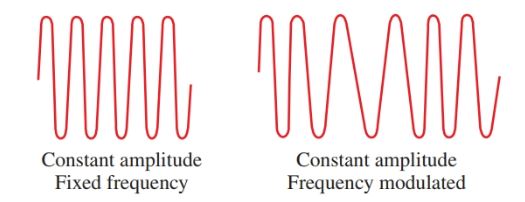
Figure 5. For FM, the frequency of the wave is varied at an audio rate.
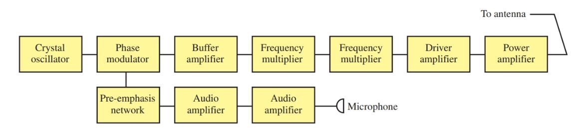
Figure 6. The block diagram of a simplified FM transmitter.
Each FM station is assigned a center frequency in the FM band. This is the frequency to which a radio is tuned, Figure 7.
The amount of frequency variation from each side of the center frequency is called the frequency deviation. Frequency deviation is set by the amplitude, or strength, of the audio modulating wave.
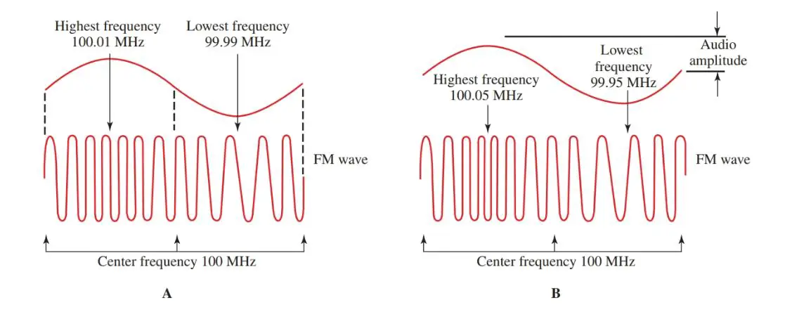
Figure 7. The amplitude of the modulating signal determines the frequency swing from the center frequency. A–Weak audio signal. B–Strong audio signal.
In part A of Figure 7, a weak audio signal causes the frequency of the carrier wave to vary between 100.01 MHz and 99.99 MHz. The deviation is ±10 kHz.
In part B of the figure, a stronger audio signal causes a frequency swing between 100.05 MHz and 99.95 MHz or a deviation of ±50 kHz. The stronger the modulation signal, the greater the frequency departure, and the more the band is filled.
The rate of frequency deviation depends on the frequency of the audio modulating signal. See Figure 8.
If the audio signal is 1000 Hz, the carrier wave goes through its greatest deviation 1000 times per second. If the audio signal is 100 Hz, the frequency changes at a rate of 100 times per second. Notice that the modulating frequency does not change the amplitude of the carrier wave.
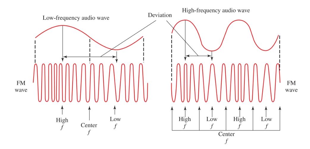
Figure 8. The rate of frequency variation depends on the frequency of the audio modulating signal.
An FM signal forms sidebands. The number of side-bands produced depends on the frequency and amplitude of the modulating signal.
Each sideband is separated from the center frequency by the amount of the frequency of the modulating signal, Figure 9. The power of the carrier frequency is reduced a great deal by the formation of sidebands, which take power from the carrier. The amount of power taken from the carrier depends on the maximum deviation and the modulating frequency.
Although a station is assigned a center frequency and stays within its maximum deviation, the formation of sidebands determines the bandwidth required for transmission.
In FM, the bandwidth is specified by the frequency range between the upper and lower significant sidebands. A significant sideband has an amplitude of one percent or more of the unmodulated carrier.
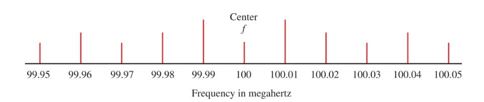
Figure 9. Sidebands generated by a 10 kHz modulating signal on a 100 MHz carrier wave.
Narrow Band FM
The maximum deviation of a carrier wave can be limited so that the FM wave occupies the same space as an AM wave carrying the same message. This is called narrowband FM. Some distortion occurs in the received signal. This is satisfactory for voice communication but not for quality music sound systems.
Modulation Index
The modulation index is the relationship between the maximum carrier deviation and the maximum modulating frequency:
\[\text{Modulation Index=}\frac{\text{Maximum Carrier Deviation}}{\text{Maximum Modulating Frequency}}\]
Using this index, the number of significant side-bands and the bandwidth of the FM signal can be figured. The complete index can be found in more advanced texts. Examples of the use of the modulation index are given in Figure 10.
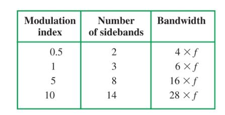
Figure 10. Examples of modulation index use. When calculating bandwidth, f is the modulating frequency.
If the amplitude of a modulating signal causes a maximum deviation of 10 kHz and the frequency of the modulating signal was 1000 Hz, the index would be:
\[Modulation\text{ }Index=\frac{10,000}{1000}=10\]
If you examine Figure 10, you can see that this FM signal would have 14 significant sidebands and occupy a bandwidth of 28 kHz.
Percent of Modulation
The percent of modulation has been set at a maximum deviation of ± 75 kHz for FM radio. The FM sound transmission in television is limited to ± 25 kHz.
Amplitude & Frequency Modulation Key Takeaways
Understanding amplitude and frequency modulation is essential for effectively transmitting audio signals across various communication systems. These techniques allow the superimposing of audio data onto carrier waves, enabling efficient use of the frequency spectrum. Key concepts like sidebands, modulation percentage, power distribution, and bandwidth requirements help engineers design systems that maximize signal clarity while minimizing interference and power loss. Applications such as AM and FM radio broadcasting, television audio transmission, and two-way communication systems rely heavily on these modulation methods.