The article provides an overview of half-wave and full-wave voltage doublers, explaining their working principles and circuit diagrams. It highlights how these circuits multiply voltage without using transformers, making them useful for low-current, high-voltage applications.
It assumed that the source of power is 117-volt ac found in homes and schools. The transformer is used to step up or step down the voltages required for the electronic circuits. Because transformers are heavy and costly, voltage multiplying circuits (voltage doublers) have been devised to raise voltages without the use of transformers.
Half-Wave Voltage Doubler Working
Study Figure 1. It shows the action in a half-wave voltage doubler circuit. In part A of Figure 1, the input ac voltage is on the negative half cycle. As a result, point A is negative. Current flows from point A, through the rectifier D1, and charges capacitor C1 to the polarity shown.
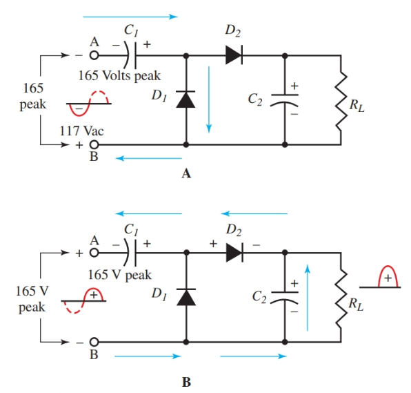
Figure 1. Half-Wave Voltage Doubler Circuit Diagram
A–During the first half cycle, C1 charges through conduction of rectifier D1.
B–During the second half cycle, applied line voltage is in series with the charge on C1. Current flows through D2. C2 gets the sum of line voltage and that from C1.
During the positive half cycle, point A is positive. The applied peak voltage of 165 volts is in series with the charged capacitor C1. In the series connection, the voltages add together. So, the output from the doubler is the applied voltage plus the voltage of C1.
Current cannot flow through the rectifier D1 due to its one-sided conduction. The output waveform shows half-wave rectification with an amplitude of about twice the input voltage. Rectifier D2 permits current to flow in only one direction to the load.
Full-Wave Voltage Doubler Working
A full-wave voltage doubler is drawn in Figure 2. During the positive peak of the ac input, point A is positive. Current flows from point B, charging C1 in the polarity shown, through D1 to point A.
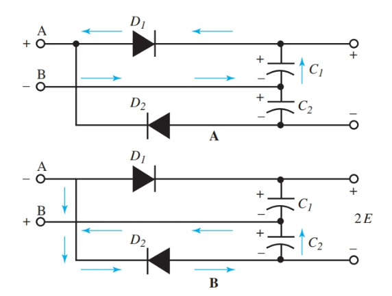
Figure 2. Full-Wave Voltage Doubler Circuit Diagram
A–C1 charges during the first half cycle.
B–C1 + C2 in series.
During the negative cycle of the input, point A is negative. Current flows through D2 to C2, charging it to the noted polarity, to point B.
Notice that during one cycle of ac input, capacitors C1 and C2 have been charged so that the voltages across C1 and C2 are in series. The output is taken from across these capacitors in series. The output voltage is the sum of both voltages or twice the input voltage.
Voltage doubler circuits provide useful high voltages for circuits needing low current. Because output voltage depends on charged capacitors, voltage regulation is poor. Conventional filter circuits are added to smooth out the voltage as in transformer rectifier circuits.
Half-Wave & Full-Wave Voltage Doubler Key Takeaways
Half-wave and full-wave voltage doublers play a vital role in electronic circuits where high voltage is required but current demand is low. Their ability to generate higher voltages without the bulk, cost, and complexity of transformers makes them ideal for lightweight and space-constrained applications, such as in TV sets, oscilloscopes, and other portable electronic devices. Despite limited voltage regulation, their efficiency and simplicity make them a practical solution in many modern electronic systems.