This article explains the fundamentals of single-ended (Class A) power amplifiers, focusing on their operating characteristics and low-distortion behavior. It introduces the concept of operational efficiency and outlines how efficiency is defined and calculated for single-ended amplifier designs.
A single-ended power amplifier is very similar in many respects to a small-signal amplifier. It is normally operated as a class A amplifier. The operating point of a class A amplifier is near the center of its active region. This causes the AC signal applied to the input to be fully reproduced in the output. As a general rule, this type of amplifier operates with a minimum of distortion. This article discusses the characteristics and design of the single-ended power amplifier.
Operational Efficiency of Single-Ended Power Amplifier
An amplifier system that has only one amplifying device that develops output power is called a single-ended amplifier. Efficiency levels for a single-ended amplifier are in the range of 30%.
Operational efficiency refers to the ratio of developed output power to DC supply power. This is often denoted by the Greek symbol η (Eta). The equation for efficiency is
$$\eta =\frac{P_{out}}{P_{in}}\times \textrm{100%}$$
For example, a class A amplifier, with 9 W of DC input power, develops 3 W of DC output power. The amplifier efficiency would be 33%.
$$\eta =\frac{P_{out}}{P_{in}}\times \textrm{100%}=\frac{3W}{9W}\times \textrm{100%}=\textrm{33%}$$
Signal-ended amplifiers, because of their low efficiency rating, are generally used only to develop low-power output signals.
Figure 1 shows a single-ended audio output amplifier. The term audio refers to the range of human hearing. Audio frequency (AF) refers to frequencies that are from 15 to 15 kHz. This particular amplifier responds to signals somewhere within this range.
A collector family of characteristic curves for the transistor used in the single-ended power amplifier is shown in Figure 2. Note that the power dissipation (PD) curve of this amplifier is 5 W. Remember that PD = IC × VCE and IC = PD/VCE. The points of IC along the curve are plotted at VCE points such as IC = PD/VCE = 5 W/25 V = 0.2 mA. The developed load lines for the amplifier are well below the indicated PD curve. This means that the transistor can operate effectively without overheating.
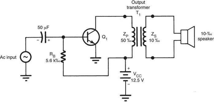
Figure 1. Single-ended Class A audio amplifier circuit diagram.
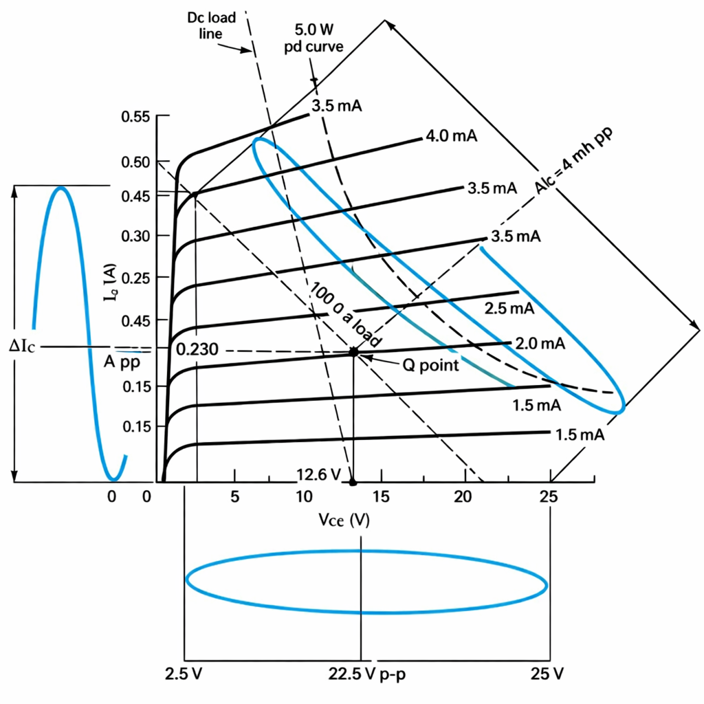
Figure 2. Collector family of characteristic curves for the single-ended audio amplifier in Figure 1.
DC and AC Load Line Analysis
Investigation of the collector family of characteristic curves of this example shows that two load lines are plotted: DC and AC. The static or DC load line is based on the resistance of the transformer primary of 50 Ω. The resistance of the DC load line is 100 Ω, based on 12.5 VCC and 1.25 mA of IC. This means that the DC load line extends almost vertically from the 12.5-VCC point on the curve. The AC load line is determined with the primary winding impedance (50 Ω) and twice the value of VCE (25 V) compared to the DC load line. The AC output signal is, therefore, twice the value of VCC. The operational points are 25 VCC and 500 mA of IC.
When an AC signal is applied to the input, it can cause a swing 12.5 V above and below VCC. The transformer, in this case, accounts for the voltage difference. A transformer is an inductor. When the electromagnetic field of an inductor collapses, a voltage is generated. This voltage is added to the source voltage. In an AC load line, VCE, therefore, swings to twice the value of the source voltage. This usually occurs only in transformer-coupled amplifier circuits. Note that the operating point (Q point) is near the center of the AC load line.
With the load line of the amplifier is established, the base resistance value must be determined. For the circuit in Figure 1, the emitter voltage is zero. The emitter—base junction of the transistor, being silicon, has 0.7 V across it when it is in conduction. The base resistor, therefore, has 12.5 – 0.7 V, or 11.8 V, across it at the Q point of the 50-Ω AC load line. By Ohm’s law, the value of RB is 11.8 V/2 mA, or 5900 Ω. A standard resistor value of 5.6 kΩ would be selected for RB. Note the location of this resistor in the circuit.
With this data, it is possible to look at the operational efficiency of the single-ended amplifier. The DC power supplied to the circuit for operation is
$$P_{in}=V_{CC}\times I_{C}=12.5V\times 0.230A=2.87W$$
The developed AC output power (Pout) is a peak-to-peak value. The VCE peak-to-peak value is 2.5–25 V, or 22.5 VPP. The IC peak-to-peak value is 0–0.45 A, or 0.45 APP.
To make a comparison in power efficiency, the peak-to-peak values must be changed to RMS values. Remember that an RMS AC value and a DC value do the same effective work. Conversion of peak-to-peak voltage to RMS is done by the following expression:
$$V_{CE(rms)}=\frac{V_{PP}}{2}\times 0.707$$
Therefore,
$$V_{CE(rms)}=\frac{V_{PP}}{2}\times 0.707 =\frac{12.5V_{PP}}{2}\times 0.707=7.954V$$
For the RMS IC value, the conversion is
$$I_{C(rms)}=\frac{I_{PP}}{2}\times 0.707 =\frac{0.45A_{PP}}{2}\times 0.707=0.159A$$
The developed AC output power (Pout) is determined by the following formula:
$$P_{out}=V_{CE(rms)}\times I_{C(rms)}=7.954V\times 0.159A=1.265W$$
The operational efficiency of the single-ended amplifier of Figure 1 is, therefore, determined by the ratio of the output power to the input power expressed as a percentage.
$$\eta =\frac{P_{out}}{P_{in}}\times \textrm{100%}=\frac{1.265W}{2.898W}\times \textrm{100%}=\textrm{43.65%}$$
This shows that an amplifier of this type is only 44% efficient. It takes 2.898 W of DC supply power to develop 1.2652 W of AC output power. This low operational efficiency does not make the single-ended amplifier very suitable for high-power applications. As a general rule, amplifiers of this type are used only where the required output is 10 W or less. The power wasted by a single-ended amplifier appears in the form of heat. Obviously, it would be very desirable to get more sound output and less heat during operation.
Example 1
In the amplifier circuit given in Figure 1, if 2.5 W of input power is used for developing 1 W of output power, calculate the efficiency of the amplifier.
Solution
$$\eta =\frac{P_{out}}{P_{in}}\times \textrm{100%}=\frac{1W}{2.5W}\times \textrm{100%}=\textrm{40%}$$
Review Questions
1. The efficiency of a class A amplifier is very high: True/False.
2. A class A amplifier is also called a __________________.
3. In a class A BJT amplifier, the operating point is located:
- In the middle of the load line
- In the saturation region
- In the cutoff region
- Below the cutoff region
4. What is the function of an output transformer in a class A amplifier?
- Pass DC signal
- Block amplified AC signal
- Impedance matching with load
- Collector biasing
5. If the load connected to the output of a class A amplifier is shorted, the AC output will
- Be 0 V.
- Will have reduced current.
- Function normally
- Be amplified.
Answer
1. False
2. Single-ended amplifier
3. In the middle of the load line
4. Impedance matching with the load
5. 0V when the output is shorted
Key Takeaways
Understanding single-ended power amplifiers and their operational efficiency is important because these amplifiers are widely used in low-power and audio applications where signal fidelity and simplicity are more critical than efficiency. Although their low efficiency limits their suitability for high-power systems, their predictable behavior, minimal distortion, and straightforward design make them valuable in instructional settings, signal amplification stages, and applications requiring high linearity.