The article explores the relationship between electricity and magnetism, focusing on fundamental concepts such as the magnetic field around current-carrying conductors, the left-hand rule, and the importance of wire placement in electrical circuits. It also introduces key principles of magnetic circuits, including reluctance, permeability, field intensity, solenoids, electromagnets, and the properties of residual magnetism and retentivity.
During the eighteenth and nineteenth centuries, a great deal of research was directed toward discovering the link between electricity and magnetism. A Danish physicist, Hans Christian Oersted, discovered that a magnetic field existed around a conductor carrying an electric current.
You can perform an experiment that shows the magnetic field around the current carrying conductor. Pass a current carrying conductor through a sheet of cardboard. Place small compasses close to the conductor. The compasses will point in the direction of the magnetic lines of force, Figure 1.
Reversing the electric current will also reverse the direction of the compasses by 180 degrees. This shows that the direction of the magnetic field depends upon the direction of the current.
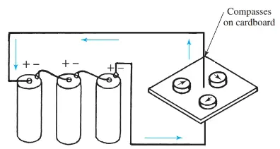
Figure 1. Compasses line up to show circular pattern of magnetic field around current carrying conductor.
The left-hand rule for conductors can be used to determine the direction of the magnetic field around a current-carrying conductor.
Grasp the conductor with your left hand, extending your thumb in the direction of the current. Your fingers curling around the conductor indicate the circular direction of magnetic field, Figure 2.
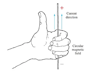
Figure 2. Left-hand rule for conductors
In Figure 3, picture the dot in the center of the conductor on the left as the point of an arrow. This shows that electric current is flowing toward you. Circular arrows show the direction of the magnetic field. This principle is very important when electrical wires carry alternating currents. This is because the placement of wires, or lead dress, has an influence on the workings of a circuit.
Conductors are grouped in pairs whenever possible to eliminate heating effects and radio interference caused by the magnetic field created by the electric current flow. The National Electric Code requires that wires be run in pairs to help eliminate this heating effect.
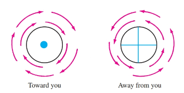
Figure 3. These conventions are used to show the link between electric current flow and the magnetic field. The dot represents a current arrow heading toward you. The cross on the right represents the tail end of the current arrow heading away from you.
Magnetic Circuits
Here, you will be introduced to the terms used to describe quantities and characteristics of magnetic circuits.
Reluctance
It has already been mentioned that a likeness exists between magnetic circuits and electrical circuits. In addition, a law for magnetic circuits exists that is comparable to Ohm’s law for electrical circuits. This law is known as Rowland’s law.
Rowland’s law states that the number of lines of magnetic flux (comparable to current in electrical circuits) is in direct proportion to the force (comparable to voltage in electrical circuits) producing them. This force (F) is in units of magnetomotive force called gilberts.
Also, there is resistance to the magnetic flux in a magnetic circuit. The resistance to magnetic flux is called reluctance. Reluctance is measured in gilberts per Maxwell or in ampere-turns per weber. One ampere-turn per weber is sometimes called a rel. In equation form:
\[\phi =\frac{F}{\Re }\]
Where ϕ = force producing the field, ℛ = resistance to the magnetic flux (reluctance).
The relationship between F in gilberts and ampere-turns is a factor of 1.257. This relationship is stated:
$F=1.257I\times N$
Where F is the force in gilberts, I is the electric current, and N is the number of turns.
The term reluctance has been defined as the unit of measurement of the resistance to the passage of magnetic lines of force. Experimentation proves that, as the flux path increases in length, the reluctance increases. Likewise, as the cross-sectional area of the flux path decreases, the reluctance increases.
Permeability and Magnetic Field Intensity
Reluctance also depends upon the material used as the path. The ability of a material or substance to conduct magnetic lines of force is called permeability.
The permeability of air is considered to be one. Materials with permeabilities higher than one conduct the lines of force better than air. Materials with permeabilities lower than one offer more resistance to magnetic lines of force.
Permeability is expressed by the Greek letter μ, (pronounced mew). The factors determining the resistance in a magnetic circuit can be compared to the factors affecting the resistance of electron flow in a conductor. For the magnetic circuit:
\[\Re =\frac{l}{\mu \times A}\]
Where ℛ is the reluctance, l is length of path, μ is the permeability of the material in the path, and A is the cross-sectional area of the path.
There is a distinct link between the density of a magnetic field, the force producing the field, and the permeability of the substance in which the field is produced. Mathematically:
\[\mu =\frac{B}{H}=\frac{\text{Flux Lines per c}{{\text{m}}^{\text{2}}}\text{ or gauss}}{\text{Gilbers per cm}}\]
The symbol H is the field intensity of a magnetizing force through a unit of length. It is commonly expressed in gilberts per centimeter. Mathematically:
\[H=\frac{F}{l}=\frac{1.257\times I\times N}{l}\]
The term l is, again, the length of path expressed in centimeters. When making calculations the B, H, and μ of common magnetic materials can be found in an electricity handbook.
The Solenoid
When a current carrying conductor is wound into a coil, or solenoid, the magnetic fields circling the conductors seem to merge or join together. A solenoid will appear as a magnetic field with a N pole at one end, and a S pole at the opposite end. This solenoid is shown in Figure 4.
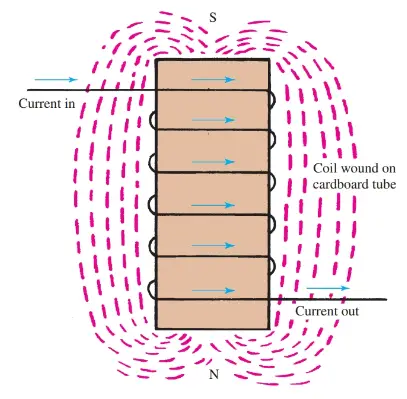
Figure 4. A wire wound into a coil is a solenoid and has a polarity set by the direction of current flow.
The left-hand rule for coils can be used to determine the polarity of the coil. Grasp the coil with your left hand in such a manner that your fingers circle the coil in the direction of electric current flow. Your extended thumb will point to the N pole of the coil, Figure 5.
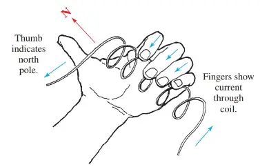
Figure 5. Left-hand rule for coils.
The strength of the magnetic field of a solenoid depends upon the number of turns of wire in the coil and the size of the current in amperes flowing through the coil. The product of the amperes and turns is called the ampere-turns (At or NI) of a coil. This is the unit of measurement of field strength.
If, for example, a coil of 500 ampere-turns will produce the field strength required for some situation, any combination of turns and amperes totaling 500 will work. Examples:
50 turns × 10 amps =500At
100 turns × 5 amps =500At
500 turns × 1 amp =500At
Electromagnets
In the solenoid just discussed, air only is the conductor of the magnetic field. Other substances conduct magnetic lines of force better than air. These materials would be described as having greater permeability.
To demonstrate this, a soft iron core can be inserted in the solenoid coil, Figure 6. The strength of the magnetic field is greatly increased. There are two reasons for this increase. First, the magnetic lines have been concentrated into the smaller cross-sectional area of the core. Secondly, the iron provides a far better path (greater permeability) for the magnetic lines. This device (solenoid with an iron core) is known as an electromagnet.
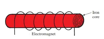
Figure 6. The coil with an iron core is described as an electromagnet.
Residual Magnetism
When an electromagnet is energized, it is a powerful magnet. When the electrical energy is disconnected, the electromagnet loses most of its magnetism, but not all of it. If the depowered magnet is brought near some iron filings, the filings will be attracted to the core because the iron core has retained a small amount of its magnetism. This magnetism is called residual magnetism.
Retentivity
If very little magnetism remains, the core would be considered as having low retentivity. Retentivity is the ability of a material to retain magnetism after the magnetizing field has been removed.
If a core retains a good deal of magnetism, it is said to have high retentivity. A soft iron core shows low retentivity. A steel core has high retentivity.
Electric Current and Magnetism Relationship Key Takeaways
Understanding the relationship between electricity and magnetism is crucial for various practical applications in electrical engineering and technology. The principles discussed, such as magnetic fields around conductors, solenoids, and electromagnets, form the foundation for designing electric motors, transformers, relays, and generators. Additionally, concepts like reluctance, permeability, and field intensity play a vital role in optimizing magnetic circuits for efficient energy transfer in power systems. The ability to control and manipulate magnetic fields is essential for modern electrical devices, from industrial automation to communication systems.