The article explains the concept of a rotating magnetic field in three-phase AC machines, its formation through stator windings, and how the number of poles and supply frequency determine the synchronous speed. It also highlights the roles of the stator and rotor in generating and responding to this rotating field.
Referring to electromagnets, if a coil is connected to a DC source a magnetic field is generated in the coil. Consider now if the source is AC with a frequency of 50 Hz. Again, a magnetic field is generated, but this time its north and South Pole swap places rapidly with the change in the current direction (100 times per second).
Now, consider three pairs of similar but separate windings that are connected to the three phases of a three-phase supply, each pair connected to one phase.
Because the voltages in the three phases are not in phase with each other, the magnetic fields, accordingly, are not reaching their maximum and minimum strength at the same instants. Figure 1 shows these windings that are physically placed 120° from each other.
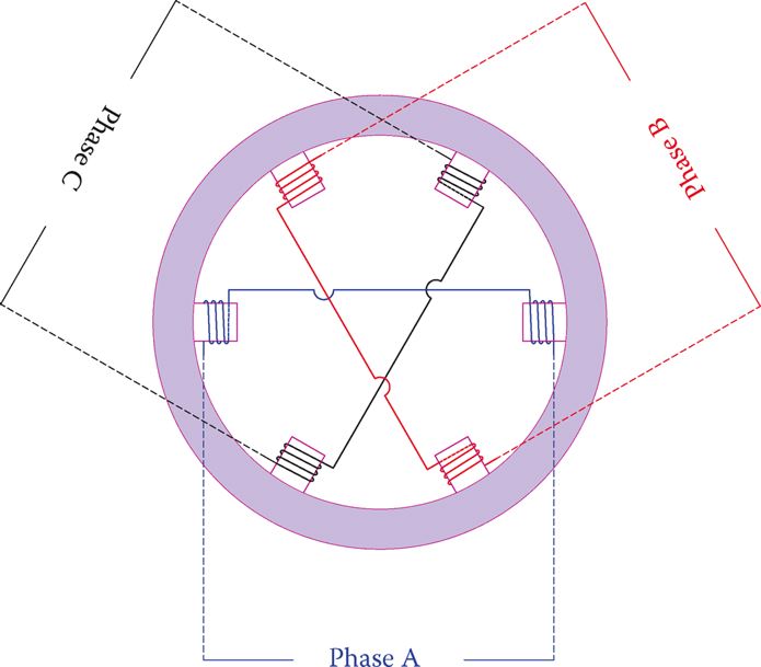
Figure 1 Three windings connected to three voltages of a three-phase system.
Because three-phase voltage has a sinusoidal pattern, the strength of each magnetic field traces a sinusoidal pattern, which continuously varies from zero to a maximum and back to zero, and then changing direction, repeating the same pattern in the opposite direction.
We may schematically show the resulting magnetic field by two opposite vectors that depict the direction and only the maximum and minimum lengths, corresponding to the peak values.
As said before, because voltages in a three-phase system are 120° out of phase, the variations of the three fields are not coincident, and their maximum and minimum values do not occur at the same time.
Figure 2 illustrates the direction of the magnetic field for the maximum positive and the maximum negative values of the current in phase A, the maximum currents for phased B and C, and for some negative current in phase B.
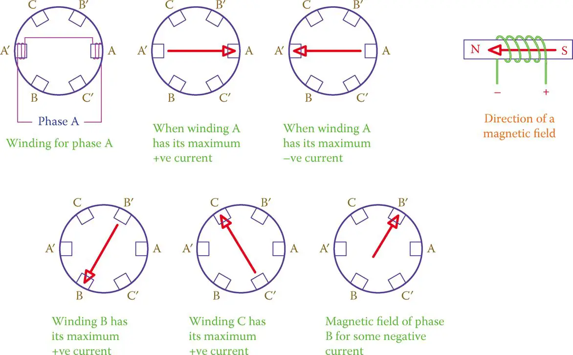
Figure 2 Direction and magnitudes of magnetic fields of windings in Figure 1 at a number of times.
At each instant of time, the resulting magnetic field is obtained by adding together the three individual magnetic fields developed in the three windings. For this addition, however, as well as the magnitude, direction of the magnetic fields must be brought into account because the windings are at 120° from each other.
In other words, addition implies the vector sum of the three magnetic fields. Because the magnetic fields are not constant, at each instant of time the resultant magnetic field has a different direction within 360°. Some of these positions are shown in Figure 3.
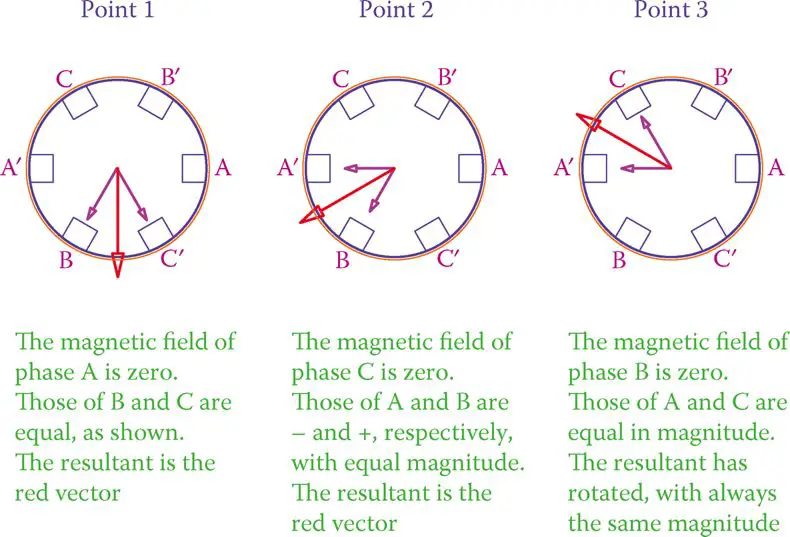
Figure 3 Illustration of three positions of the rotating magnetic field.
It can be graphically and mathematically shown that the resultant has the same magnitude, but its direction continuously changes. In fact, it can be seen that the resulting magnetic field rotates with time.
The speed of rotation is constant and for the arrangement in Figure 1 (one pair of windings for each phase) is the frequency of the AC line. That is, if the line frequency is 50 Hz, the speed of the rotating magnetic field is 50 revolutions per second.
For three winding pairs, as was the case in Figure 1, for each one cycle of current, the resulting magnetic field rotates by one revolution. The same arrangement can be practiced with two sets of windings (six pairs) connected to three phases in a correct order and each one being physically at 60° from the neighboring windings (instead of 120°). In such a case, it can be seen that for each full cycle of current variation the magnetic field revolves half a revolution.
By increasing the number of windings and connecting them in a proper manner, the number of revolutions per second of the magnetic field can be modified. This is what is done in AC machines to change the operating rpm.
Synchronous Speed Formula
The relationship between the number of poles (each pair of windings counts for one set of north and south poles) and the rotating speed is
\[\begin{matrix} {{N}_{s}}=\frac{60f}{p} & {} & \left( 1 \right) \\\end{matrix}\]
- More on Speed Calculation: How to Calculate Synchronous Speed
In this equation, NS is the rotational speed in revolutions per minute (rpm), f is the line frequency in Hertz, and p is the number of pairs of poles per phase. That is, for six windings as shown in Figure 1, for instance, p is equal to 1. The subscript S in NS represents the synchronous speed.
For any AC machine, synchronous speed is determined by the frequency of the line it is connected to because the number of poles is a physical constant when the machine is built.
In some machines the arrangement of poles can be modified; in such a case a machine can have two speeds (one twice the other). This is done outside the machine by a special switch.
Synchronous speed: Special speed for an AC machine depending on its number of poles and the frequency of the AC line.
In three-phase machines, a rotating magnetic field is developed by the stator windings. For higher-speed machines (lower number of poles), poles are distinct, but for a higher number of poles, windings are distributed around the periphery of a cylindrical support.
The set of windings forming the magnetic poles is called the stator. These windings do not rotate but create the rotating magnetic field. Figure 4 shows the stator winding of a three-phase generator.
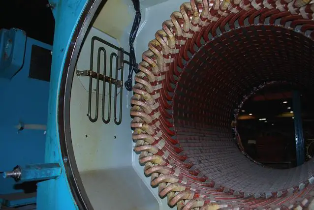
Figure 4 Stator windings of a three-phase generator.
The generated magnetic field has its strongest effect in the cylindrical space inside the winding, where the rotor is inserted, and its axis of rotation coincides with the stator axis.
Stator: Stationary part of AC electric machines, as opposed to the rotor that rotates.
The direction of rotation of the magnetic field depends on the order the windings are connected to a three-phase circuit. If (any) two connections are interchanged, the direction of rotation of the magnetic field reverses.
Rotor
The rotating part of an AC machine is called a rotor. It has a cylindrical form and is supported by bearings; it resides inside the stator and has a very small clearance from the inner diameter of the stator windings.
Remember that in DC machines two different terms are normally used instead of stator and rotor.
Figure 5 illustrates a cutaway of a three-phase machine; notably, it shows the rotor that sits inside the rotating magnetic field. This machine is much smaller than that in Figure 4, and all the inside components are on the same frame, whereas for large machines each component is separately supported.
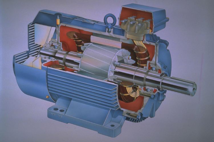
Figure 5 Cutaway of a three-phase motor. (Courtesy of ABB Inc.)
Most small machines have fins at one end of the rotor structure, which functions as a blower when rotating, forcing air across the hot components (mainly the stator windings) in order to carry the heat away. This is also shown in Figure 5.
Rotor: The rotating parts of any motor, generator, turbine, and so on. In a propeller-type turbine, the motor consists of the hub and the blades.
If (any) two connections of a three-phase system to the stator of an AC machine are interchanged, a direction of rotation of the rotating magnetic field reverses.
In order for AC machines to work, the stator must be connected to electricity. Unlike DC machines, it is not necessary to also connect the rotor to electricity. When this connection is made, a rotating magnetic field is created inside the body of the stator. It is like a rotating magnet that can pull and move ferrous metals with it.
The stationary part of an AC machine is called the stator.
Synchronous Speed Calculation Example 1
The stator of a three-phase AC machine has a total of 24 poles. What is the rotating speed of the magnetic field developed in this machine when it is connected to 60 Hz line?
Solution
Because the machine is three-phase, the number of poles per phase is 8. Because poles have to be in pairs of north and south, then there are four pairs of poles; thus, p = 4. Using p = 4 and f = 60 in Equation 1 gives
\[{{N}_{s}}=\frac{60f}{p}=\frac{60\times 60}{4}=900rpm\]
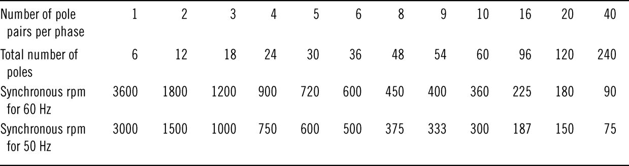
Table 1 Synchronous Speed for Various Number of Poles
Rotating Magnetic Field in AC Machines Key Takeaways
Understanding the concept of a rotating magnetic field is crucial for the design and operation of three-phase AC machines, such as motors and generators. This rotating field, formed through the strategic placement and energizing of stator windings, directly governs the behavior and efficiency of the rotor. By manipulating the number of poles and the supply frequency, engineers can precisely control the synchronous speed of the machine, which is essential in a wide range of industrial and commercial applications. These principles enable reliable power generation, efficient electric motor performance in automation systems, and adaptable control in electric vehicles and HVAC systems.