The article covers the operation, purpose, and ratings of fuses, guidelines for replacement, and various types of fuses used in electronic and electrical applications, including cartridge, Type T, Type S, blade, and electronic fuses.
What is a Fuse?
A fuse is a protective electrical device designed to safeguard circuits and equipment from overcurrent conditions, such as short circuits or overloads. It consists of a metallic wire or strip that melts when the current flowing through it exceeds a predefined value, thereby interrupting the flow of electricity and isolating the faulty section of the circuit. Fuses are widely used because they are simple, cost-effective, and reliable for protecting electrical systems.
Key Features of a Fuse:
- Current Rating: The maximum current a fuse can handle before it operates (melts).
- Breaking Capacity: The maximum fault current a fuse can interrupt safely without damage.
- Speed of Operation: Fuses can be fast-acting or time-delay depending on the application.
- Replaceable: Once the fuse operates, it needs to be replaced to restore the circuit.
Fuses are essential in both low-voltage and high-voltage systems, providing protection for household appliances, industrial machinery, and electrical networks.
How Does a Fuse Work?
In some ways, a fuse is like a normally closed switch. A fuse is designed to allow current to pass under normal circumstances. However, unlike a normally closed switch, a fuse is designed to open automatically if the current exceeds is specified value. The simplest type of fuse and its schematic symbols are shown in Figure 1.
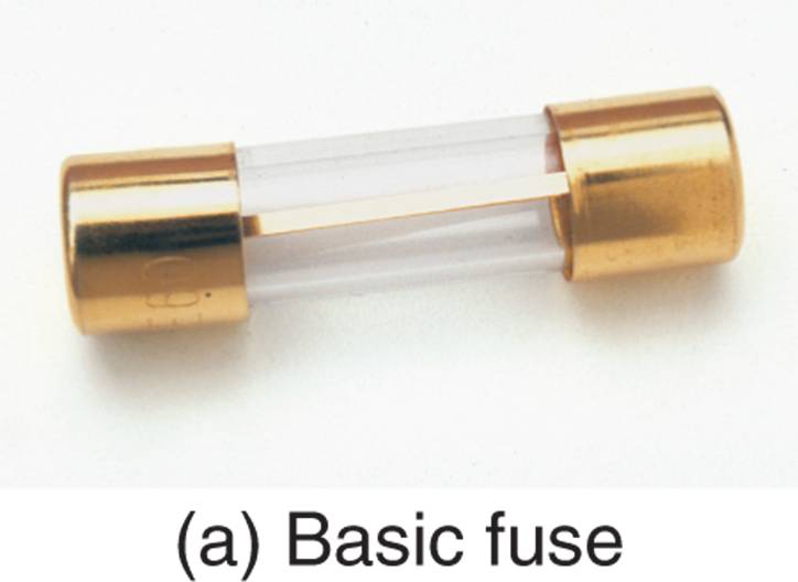
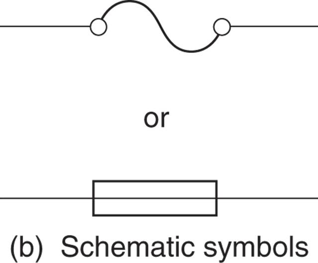
FIGURE 1 A cartridge fuse and its schematic symbol
As current passes through a conductor, heat is produced. The amount of heat varies directly with the value of current. That is, as current increases, so does the amount of heat it produces.
The fuse in Figure 1 is called a Cartridge Fuse. It contains thick conductor that is designed to melt at relatively low temperatures. If the current through the component reaches a specified level, the conductor heats to its melting point. When it melts, the connection between the ends of the fuse is broken, the fuse is destroyed, and it effectively acts as an open switch.
The purpose of the fuse is to protect a circuit or system from excessive current. For this reason, a fuse is normally placed between a power source and the circuit or system it is designed to protect, as shown in Figure 2. As you can see, the total circuit current provided by the power source in Figure 2 passes through the fuse.
As long as the fuse is good, the current path is complete. However, if the problem develops that causes the circuit current to exceed the rating of the fuse, the component opens and the current path is broken. This protects the circuit from excessive current.
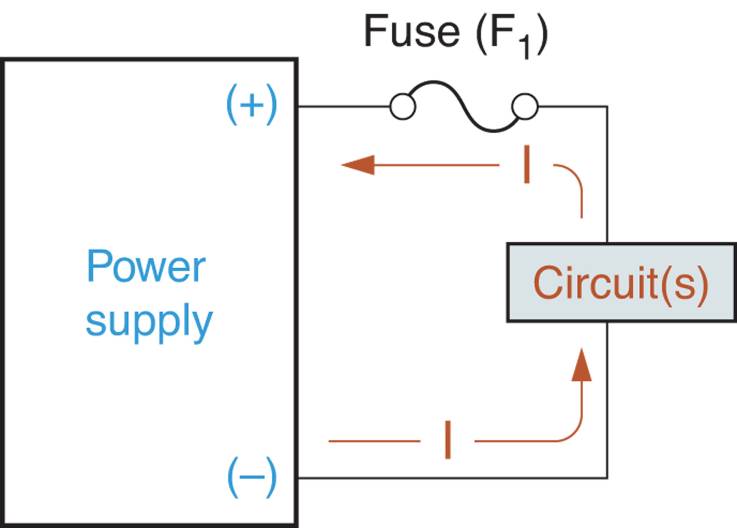
FIGURE 2 Fuse position in a basic circuit.
How to Select the Correct Fuse Rating?
Fuses have a current rating and a voltage rating.
The current rating of a fuse is the maximum allowable fuse current. If the current rating of a fuse is exceeded, the fuse will “Blow” (open).
In order for you to understand the voltage rating of a fuse, we must establish one of the characteristics of an open circuit. In an open circuit, the applied voltage is felt across the open. For example, consider the circuit shown in Figure 3a. The applied voltage has a value of 50 VDC. A difference of potential exists between points A and B. This difference of potential is equal to the applied voltage, 50 VDC.
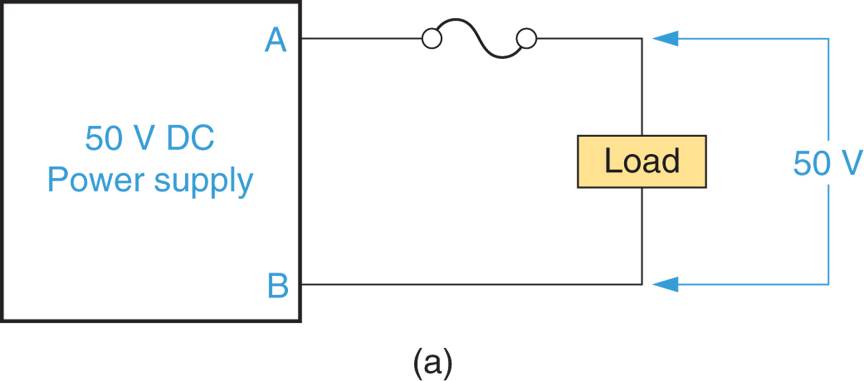
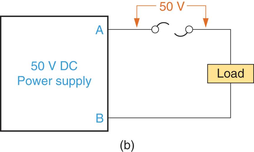
FIGURE 3 Circuit voltages with a good fuse and an open fuse.
The voltage rating of the fuse is the maximum amount of voltage that an open fuse can block.
The explanation of this rating starts with the circuit in Figure 3b. As you can see, the fuse in the circuit has opened. Once it has opened, the applied voltage (50 VDC) is felt across the fuse.
You may recall that the average breakdown voltage of an insulator is the difference of potential that will cause the insulator to break down and conduct. The voltage rating of a fuse is basically the same thing.
If the voltage across an open fuse exceeds its voltage rating, the air in the fuse may ionize (charge), causing the open fuse to conduct again. For example, consider the two circuits in Figure 4. In Figure 4a, the applied voltage is less than the voltage rating of the fuse.
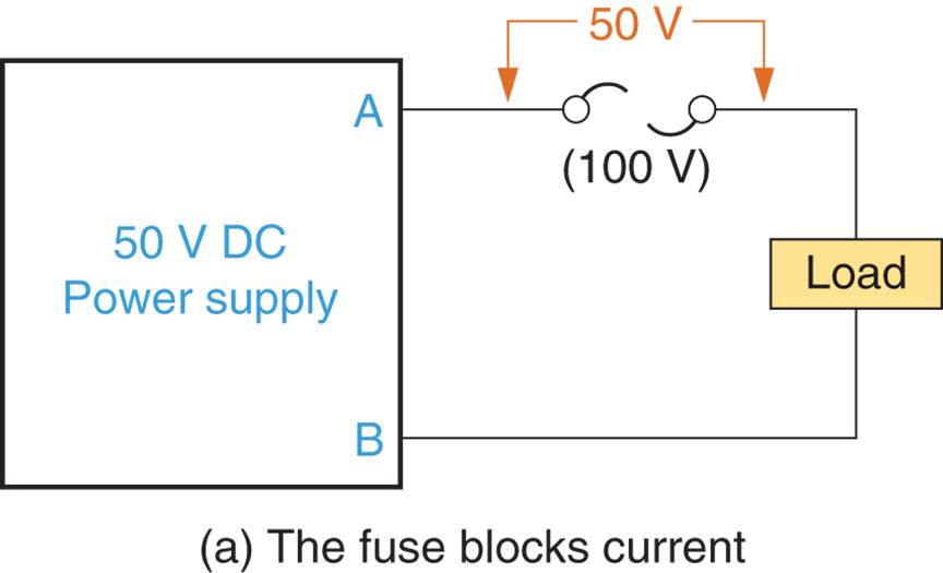
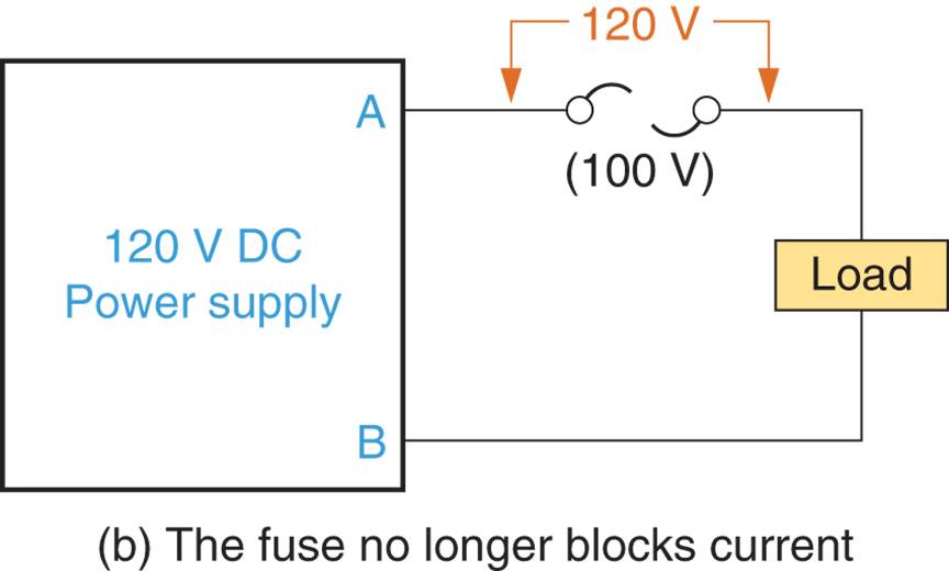
FIGURE 4 Voltages across open fuses.
In this case, the open fuse does not allow conduction, and the circuit is protected. However, the applied voltage in Figure 4b is greater than the voltage rating of its fuse. Because of this, the open fuse ionized and conducts. The result is that the circuit is no longer protected.
Formula to Determine Fuse Size
The general formula for calculating the fuse size is:
$$\text{Fuse Rating (A)} = \text{Load Current (A)} \times \text{Safety Factor}$$
Key Factors in the Formula
- Load Current (A):
The continuous operating current of the circuit or device that the fuse is protecting. This is typically the rated current of the load. - Safety Factor:
A multiplier (usually 1.25 or 125%) is applied to ensure the fuse doesn’t blow under minor current surges or normal variations.
Example Calculation
Assume a load current of 8 Amps in a circuit:
- Apply the safety factor:
$$\text{Fuse Rating (A)} = 8 \, \text{A} \times 1.25 = 10 \, \text{A}$$
Thus, the appropriate fuse size is 10 Amps.
Special Considerations for Different Applications
- General Electrical Circuits __ A safety factor of 25 is typically sufficient.
- Motor Circuits __ Motors have high inrush currents during startup, often 5–7 times the normal running current.
- In such cases, time-delay (slow-blow) fuses are used to allow for temporary surges without blowing.
- Sensitive Electronics __ For electronic devices, fast-acting fuses are preferred to protect components from short circuits or sudden spikes.
The formula $\text{Fuse Rating} = \text{Load Current} \times 1.25$ is widely used to size fuses. By applying a 25% safety margin, the fuse can handle minor overloads without unnecessary interruptions while still providing protection to the circuit. Always round up to the nearest standard fuse size for practical applications.
How to Replace a Fuse in a Circuit?
When a fuse is blown, it must be replaced. When replacing a fuse, these guidelines must be followed:
1. Make sure the circuit is de-energized. For example, if you’re replacing the fuse for a central air conditioning unit, make sure that the unit is switched off at the thermostat.
2. Use an exact replacement. That is, use a fuse that is the same size and has the same current rating as the original fuse.
3. Never replace a fuse with the one that has a higher current rating!
The first of three guidelines is designed to protect both you and the circuit. Replacing the fuse with the system energized can result in surge of current. Not only could this surge hurt you, it could also severely damage the system. The second guideline needs no explaining. A replacement fuse should never allow a higher current then the original fuse.
The third guideline is critical. If you replace a fuse with one that is higher current rating, you run the risk of damaging the circuit and potentially starting a fire. As you know, current produces heat. If you replace a fuse with one that has a higher current rating, a problem could cause more current to be drawn through the circuit than it was designed to handle. The resulting heat could destroy the circuit and could even result in fire.
Once the fuse has been replaced, one of two things will happen:
1. The circuit operation will return to normal, or.
2. The new fuse will blow when power is restored.
If the circuit operation returns to normal, then the problem was likely nothing more than an old or defective fuse. If the new fuse blows, then there is a problem that is causing excessive current to be drawn from the power source. In this case, the problem must be diagnosed and repaired before attempting to replace the fuse again.
Types of Fuses in Electronic Applications
Three types of fuses are found in electronic systems; high speed instantaneous, normal instantaneous and time delay. As you have probably guessed, these categories rate fuses in terms of the time required for them to blow.
High speed instantaneous fuses react faster to an OVERLOAD (excessive current) condition, than any other type of fuse. High speed instantaneous fuses are also known as fast acting or quick acting fuses.
Normal instantaneous fuses are somewhat slower to respond to an overload condition. Normal instantaneous fuses are also known as instantaneous or normal blow fuses.
Time delay fuses have the same time lag ratings as normal blow fuses, but they can handle short term overloads without blowing. Many applications (such as microwave ovens) produce a current surge when they turn on. If the time delay fuse is in the circuit of such an appliance, the current surge will not blow the fuse, Note that time delay fuses are also known as lag or slow blow fuses.
Fuses come in a variety of types and sizes, as described in Table 1. Note that the type, current, voltage ratings are commonly identified on the body or the fuse.
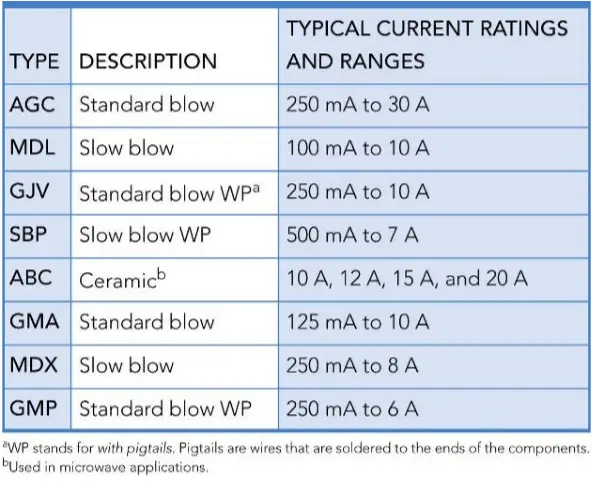
Table 1. Types and Sizes of Common Cartridge Fuses
Types of Fuses in Electrical Applications
Electrical fuses are contained in fuse boxes like the one shown in Figure 5. When a working fuse is installed, it connects the AC line input to the rest of the circuit.
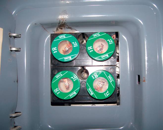
Figure 5. A fuse panel diagram
There are several types of fuses; cartridge, type T, type S, and blade. The fuses described previously are all cartridge fuses, as shown in Figure 1, a cartridge fuse is the one that has a tube shaped body.
A Type T Fuse has an Edison base. As shown in Figure 6a, the Edison base resembles the base of a light bulb. This type of fuse screws directly into a standard fuse socket.
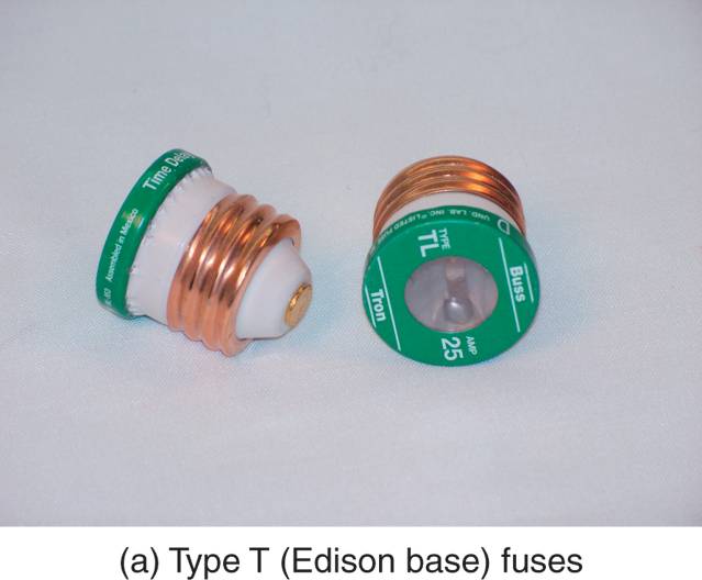
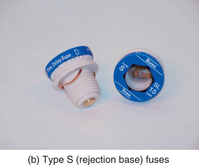
Figure 6. Common electrical fuses. (a) Type T Fuse. (b) Type S Fuse
A Type S Fuse is shown in Figure 6b. The base on the type S fuse is called a rejection base. A rejection base requires the use of an adaptor is installed in a fuse socket. Once the rejection base adaptor is installed in a fuse socket, it cannot be removed.
Type S fuses with different current ratings have different threads. For example, a 30A fuse will not fit in the adaptor for a 15A fuse. This makes it impossible for the type S fuse to be replaced by one with a different current rating. Note that rejection bases are also referred to as Tamperproof bases. The basic characteristics of Type T and Type S fuss are summarized in Table 2.
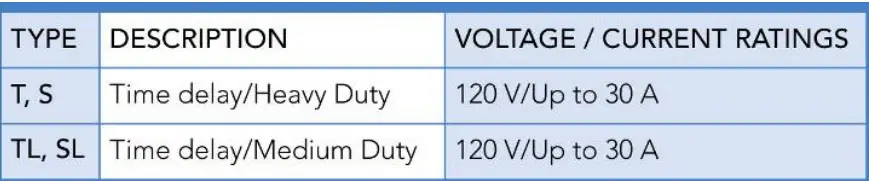
Table 2. Voltage and Current Ratings of Type T and Type S Fuses
Blade fuses are commonly used in automotive applications. Several blade fuses and fuse holders are shown in Figure 7.
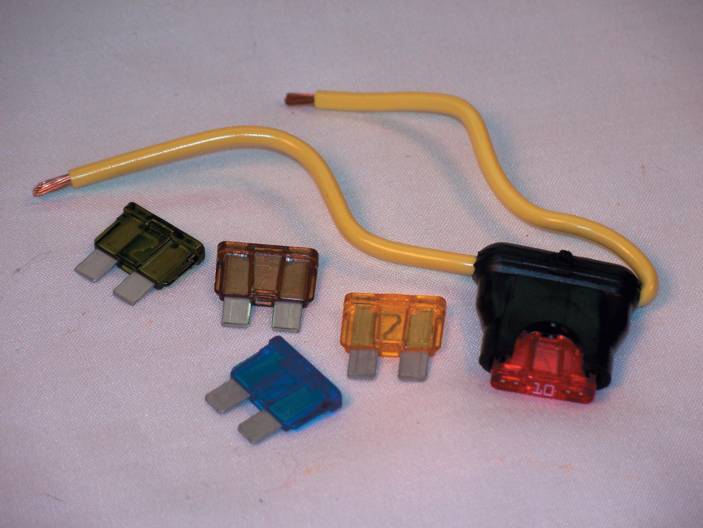
FIGURE 7 Blade fuses and fuse holder.
Summary
Types of Fuses Key Takeaways
- A fuse is a component that allows current to pass so long as it remains below the fuse current rating.
- If circuit current exceeds the fuse rating, the fuse opens (blows) and current is blocked.
- Fuses are rated for both current and voltage. The current rating is the maximum current the fuse will allow before it opens. The voltage rating is the maximum voltage that the fuse can withstand before it begins to conduct even if it is blown.
- A T-type fuse screws into a service panel in the same way as a light bulb. This is referred to as an Edison base. An S-type fuse has what is called a rejection base, and requires an adaptor to fit into a standard fuse socket. Different fuse ratings have different threads, so you cannot install the wrong fuse in this socket.