Ohm’s Law Definition
Ohm’s law states that the current in an electric circuit is proportional to the applied voltage and inversely proportional to its resistance.
As the voltage increases in a circuit (resistance remaining constant), the current increases by the same amount. Hence, if the voltage is doubled, the current will double. Also, the amount of current in a circuit is inversely proportional to its resistance when the voltage remains unchanged.
Stated another way, if the resistance in circuit increases, the amount of current will decrease. For example, if the resistance is increased three times, the current will be reduced to one-third of its original value (voltage remaining constant).
Ohm’s Law Formula
It is convenient to express ohm’s law by the following simple equation:
$I(ampere)=\frac{E\text{ }(volts)}{R\text{ }(ohms)}\text{ }\cdots \text{ }(1)$
By simple algebra, equation (1) can be restated in terms of resistance or voltage as follows:
$R=\frac{E\text{ }}{I}\text{ }\cdots \text{ }(2)$
$E=IR\text{ }\cdots \text{ (3)}$
Here is another way of expressing ohm’s law:
An electrical pressure of one volt across a resistance of one ohm will cause one ampere of current to flow.
Ohm’s Law and Non-Linear Resistors
Since R is constant, equation (3) is the equation of a straight line, for this reason, the resistor is called a linear resistor. A graph of v versus I is shown in figure 1, which is a line passing through the origin with a slope of R. Obviously, a straight line is the only graph possible for which the ratio of v to I is constant for all i.
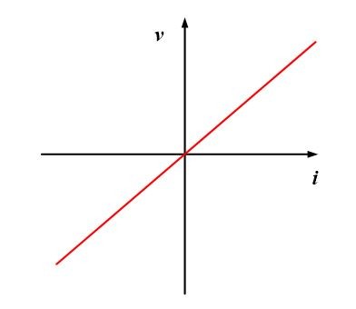
Fig.1: voltage-current characteristic for a linear resistor
- You May Also Read: Nonlinear Resistor Characteristics
Resistors whose resistances do not remain constant for different terminal currents are known as non-linear resistors. For such a resistor, the resistance is a function of the current flowing in the device. A simple example of a non-linear resistor is an incandescent lamp. A typical voltage-current characteristic for this device is shown in figure 2, where we see that the graph is no longer a straight line. Since R is not a constant, the analysis of a circuit containing nonlinear resistors is more difficult.
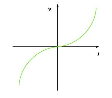
Fig.2: typical voltage-current characteristic for a non-linear resistor
In reality, all practical resistors are non-linear because the electrical characteristics of all conductors are affected by environmental factors such as temperature. Many materials, however, closely approximate an ideal linear resistor over a desired operating region.
Ohm’s Law: Solving for Current
A simple electric circuit is shown in pictorial form in figure 3 so that you can see the physical relation of the several components. Generally speaking, schematic diagrams rather than pictorial diagrams are used in electronics work. The diagram shown in Figure 4 represents schematically the pictorial drawing in figure 3.
Fig.3: Pictorial Diagram of Simple Electric Circuit
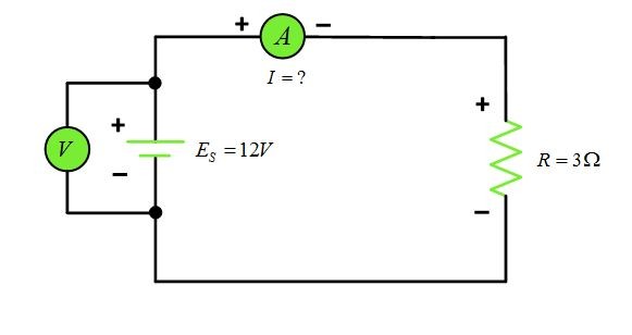
Fig.4: Schematic Diagram of Series Circuit
Observe the polarity of the ammeter connections in figure 4. note that the positive terminal of the ammeter connects to the positive terminal of the battery, while the negative terminal connects to the resistor: Note also that the ammeter is connected in series with the resistor so that all the current in the circuit must pass through it. Because ammeters have very low resistance, they do not materially increase the circuit resistance. If an ammeter were accidentally connected across (in parallel with) the battery or resistor, a very large current would momentarily flow and would likely to damage the meter.
Connected across the battery is a voltmeter to read the battery voltage. Because voltmeters are normally very high resistance instruments, they do not draw any significant amount of current from the battery. Observe the polarity of the voltmeter connections. The positive lead connects to the positive terminal of the battery, while the negative lead connects to the battery’s negative terminal. A very important rule to remember is that voltmeters are always connected in parallel with a voltage source or load, while ammeters are always connected in series with the circuit or load.
Here is an example to illustrate how Ohm’s law can be used to solve for the current in a series circuit.
Ohm’s Law Example 1
Determine the current in a simple series circuit shown in figure 4 from the information given?
Solution
Use the Ohm’s law formula for finding current:
$I\text{=}\frac{E\text{ }}{R}$
Substitute known values into the formula:
$I=\frac{12\text{ }}{3}=4A$
Therefore, 12 V connected across a resistance of 3Ω results in a current of 4 A through the resistor. In this case, the ammeter will read 4A.
Ohm’s Law: Solving for Resistance
The resistance of an electric circuit can be easily determined by using the Ohm’s law formula previously given and solving for resistance, as follows:
$R=\frac{E\text{ }}{I}\text{ }$
This formula tells us that the resistance in a circuit is inversely proportional to the amount of current. If the current is small, the circuit resistance must be large, assuming that the voltage remains constant. The following example illustrates the use of this formula:
Ohm’s Law Example 2
Refer to figure 5, determine the ohmic value of the load resistance RL from the data given.
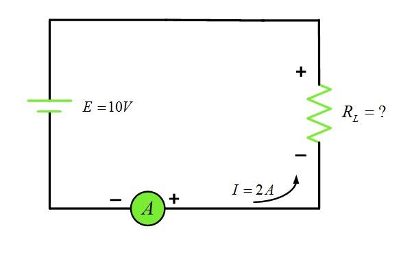
Fig.5: Determining Resistance in a Series Circuit
Solution
Use equation (2) and substitute known values:
${{R}_{L}}=\frac{E\text{ }}{I}\text{=}\frac{10}{2}\text{=5}\Omega \text{ }$
The circuit would be considered a relatively low resistance circuit because 2A is flowing with only 10 V applied.
Ohm’s Law: Solving for Voltage
If the resistance and current of the circuit are known, it is an easy matter to calculate the amount of applied voltage. We use the Ohm’s Law formula and solve for voltage:
$E=IR\text{ }$
From this formula, we can see that the voltage is the product of current and resistance. The voltage drop across a resistance, or circuit, will vary directly with either the current or resistance. For example, if a current through a resistor is doubled, the voltage drop (IR drop) will double. Or if the current can be maintained at a given value but the resistance is doubled, the voltage drop will double. The following example shows how to calculate voltage, or IR, drop.
Ohm’s Law Example 3
Determine the value of the supply voltage in the circuit of figure 5 from the information given.
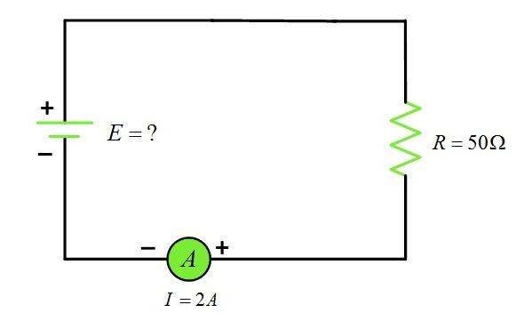
Fig.6: Calculating E when R and I are known
Solution
$E=IR=2*50=100V$
Hence, from example, we see that it requires 100 V supply to force 2A current through a 50 Ω resistor. We can say that the IR drop across the resistor is 100V, the same as the supply. No IR drop occurs across the ammeter since its resistance is assumed to be zero for all practical purposes.
Ohm’s Law Graphical Representation
Previously, we learned that the current in a circuit is directly proportional to the applied voltage and inversely proportional to the resistance. If the voltage is doubled, the current will increase two times assuming the resistance remains constant. This linear relationship is shown by the top diagonal straight line in figure 7, which is a graph of the equation I=V/R for a resistance of 20 Ω. Note that the voltage is plotted on the horizontal axis and the current on the vertical axis.
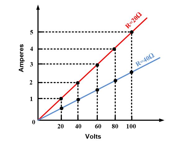
Fig.7: Linear Relationship between Current and Voltage in a Constant-Resistance Circuit
If we had assumed load resistance of 40 rather than 20 Ω, the diagonal line marked R=40Ω would be the result. If a resistance less than 20 Ω has been used, the resulting line would have been steeper than the one for the 20 Ω load. The curves in figure 7 show the direct proportionality between voltage and current for different values of load resistances.
Ohm’s Law Memory AID
Ohm’s law can be easily remembered by using the simple memory aid shown in figure 8. By covering any one of the letters, you obtain the arrangement of the other two on the right-hand side of the formula for determining the value of the covered letter.
- By placing a finger over the I gives E/R, indicating that I=E/R.
- By covering the letter E leaves IR, indicating that E is the product of IR.
- Similarly, if R is covered, E/I remains, signifying that R equals E divided by I.
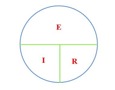
Fig.8: Memory Aid for Learning Ohm’s Law
Ohm’s Law Applications
- Ohm’s law is useful, in linear circuits, to calculate voltage, current and resistance If we know two of them
- Power calculations become easier.
https://www.youtube.com/watch?v=OGI-065RhFo
Test your understanding; answer these checkup questions.
- What is the basic formula for ohm’s law? What are the two derivations of this formula?
- What current flows in a circuit with 100 V and 1000 Ω resistance?
- What voltage is required to produce 2A of current through 60 Ω?
- What resistance will limit current flow to 4A in a circuit having a 200V supply?
- The resistance of a circuit remains the same, but the current through the resistor suddenly triples. What has happened to the circuit voltage?
- If the voltage applied to a circuit is doubled but the resistance remains unchanged, what will the current value do?
- If R triples and E doubles, what will be the new current value?
Answers to Check up Quiz
- I=E/R B. R=E/I C. E=IR
- 0.1 A
- 120V
- 50Ω
- It has tripled
- Double
- Two-thirds the original
V = I × R
Amps
Ohms
R = V / I
Volts
Amps
I = V / R
Volts
Ohms
P = V × I
Volts
Amps
I = P / V
Watts
Volts
V = P / I
Watts
Amps
Ohm’s Law Key Takeaways
In conclusion, Ohm’s Law is fundamental in understanding the behavior of electrical circuits. Its applications are crucial in various fields, especially in designing and analyzing circuits, power distribution, and electronic devices. By using the simple formulas provided by Ohm’s Law, engineers and technicians can easily calculate essential circuit parameters, such as voltage, current, and resistance. This law is especially vital in linear circuits, where it helps simplify power calculations and optimize performance. Additionally, understanding non-linear resistors further enhances the accuracy of circuit analysis, allowing for more efficient designs.