This article provides an overview of resistor power rating, explaining their significance, calculation, and the factors influencing them. It discusses common power rating categories, selection criteria for circuit design, and practical considerations such as derating and cooling mechanisms to ensure safe and reliable resistor operation.
What is Resistor Power Rating?
The resistor power rating refers to the maximum amount of power a resistor can safely dissipate as heat without being damaged or experiencing performance degradation. It is an essential specification in selecting a resistor for a circuit, ensuring that the resistor can handle the electrical energy converted into heat without failure.
Understanding Power Rating
The power dissipated by a resistor is determined using the formula:
$$P = I^2 \cdot R$$
or
$$P = \frac{V^2}{R}$$
Where:
- P : Power (in watts)
- I : Current through the resistor (in amperes)
- V : Voltage across the resistor (in volts)
- R : Resistance (in ohms)
The power rating of a resistor is usually specified in watts (W) and indicates the maximum power it can dissipate continuously under standard conditions.
One watt is the power dissipated when one ampere flows under one volt of applied emf.
Why is Power Rating Important?
The power rating of a resistor is crucial because exceeding it can lead to severe consequences for the resistor, the circuit, and even safety. Here’s a detailed breakdown of the potential problems that arise when a resistor is forced to dissipate power beyond its specified rating:
Excessive Heat Generation
A resistor converts electrical energy into heat as it limits current flow. If the power dissipation exceeds its rating, the amount of heat generated will surpass what the resistor is designed to handle.
Consequences
- Overheating: The resistor’s temperature will rise significantly.
- Failure: Prolonged overheating may cause the resistor to stop functioning completely.
- Impact on Surrounding Components: Excessive heat can also affect nearby components, leading to potential damage to the circuit.
Example. Consider a 0.5 W resistor that is forced to dissipate 1 W of power. It will quickly heat up, potentially reaching temperatures beyond its tolerance limit, leading to breakdown.
Material Damage
Resistors are made of specific materials (e.g., carbon film, metal oxide, or wire-wound) that degrade under extreme heat. Overheating due to excess power dissipation can chemically or physically alter these materials.
Consequences
- Change in Resistance: The resistor’s resistance value may drift from its intended value, affecting the circuit’s performance.
- Structural Damage: The resistor’s coating or body may crack or deform, making it unusable.
Example. A carbon film resistor might burn or develop cracks in the resistive layer, leading to erratic behavior or complete failure.
Fire Hazard
If the resistor continues to dissipate excessive power, the heat generated may ignite the materials of the resistor or nearby components.
Consequences
- Fire or Smoke: This poses a serious safety risk, especially in sensitive applications like medical devices or home appliances.
- System Failure: In critical systems, such failures can lead to catastrophic results (e.g., shutdowns, malfunctions).
Example. In a high-current application, if a resistor with an inadequate power rating overheats and ignites, it can create a chain reaction damaging the entire circuit or device.
Common Power Ratings of Resistors
Resistors come in a range of power ratings designed to suit different applications, from small electronic circuits to industrial systems. These ratings define the maximum power the resistor can safely dissipate. Choosing the right power rating ensures that the resistor operates reliably without overheating or failing. Here’s an expanded explanation of the different categories of resistor power ratings:
Small Resistors
Power Ratings: Typically range from fractions of a watt, such as 1/8 W, 1/4 W, or 1/2 W.
Applications
- Used in low-power applications, such as signal processing, sensors, or small control circuits.
- Common in consumer electronics like smartphones, watches, and low-power LEDs.
Characteristics
- Small physical size to match their low power dissipation requirements.
- Ideal for densely packed circuits where space is a constraint.
Larger Resistors
Power Ratings: Range from 1 W to 10 W.
Applications
- Suitable for higher power circuits, such as audio amplifiers, power supplies, and lighting circuits.
- Often used where moderate current flows and heat dissipation is manageable.
Characteristics
- Larger physical size and often mounted on heat sinks or have improved airflow.
- Available in various forms, including wire-wound and metal oxide resistors for enhanced heat tolerance.
High-Power Resistors
Power Ratings: Typically rated at 50 W or more. Some can even exceed 500 W in heavy-duty industrial applications.
Applications
- Common in industrial equipment, motor controllers, and renewable energy systems (e.g., solar inverters, wind turbines).
- Used for high-current or high-voltage circuits where significant power dissipation is expected.
Characteristics
- Robust construction with materials designed for extreme heat tolerance.
- May include advanced cooling features like built-in heat sinks or liquid cooling.
| Resistor Type | Typical Power Ratings | Applications | Physical Characteristics |
|---|---|---|---|
| Small Resistors | 1/8 W, 1/4 W, 1/2 W | Signal processing, sensors, small LED circuits, consumer electronics | Compact, suitable for space-constrained areas. |
| Larger Resistors | 1 W, 5 W, 10 W | Power supplies, audio amplifiers, lighting circuits | Bigger size, often requires heat management. |
| High-Power Resistors | 50 W and above | Industrial machinery, motor controllers, renewable energy systems | Large, robust, may include heat sinks or cooling systems. |
Table 1. Common Power Ratings
Factors Affecting Power Rating
The power rating of a resistor is influenced by several factors that determine its ability to dissipate heat safely. These factors guide engineers in selecting the appropriate resistor for a given application and maintaining its reliability under operational conditions. Let’s explore these factors in more detail:
Physical Size
The size of a resistor is directly proportional to its power dissipation capability. Larger resistors have more surface area, allowing for better heat dissipation into the surrounding environment.
Implications
- Small resistors, like surface-mount resistors, typically handle only fractions of a watt.
- Larger resistors, such as wire-wound types, can dissipate several watts or more.
Design Considerations
- In space-constrained circuits, small resistors must be carefully chosen to avoid exceeding their power rating.
- Larger resistors may require more space but provide greater safety margins for heat dissipation.
Material
The material used in the construction of a resistor greatly affects its heat tolerance and power handling. Common materials include:
- Carbon Film: Suitable for low-power applications but less tolerant to heat.
- Metal Oxide: Offers higher thermal stability and is often used in moderate-power applications.
- Wire-Wound: Excellent for high-power applications due to the robust construction and superior heat dissipation.
Implications
- Choosing the right material ensures the resistor can handle heat without degrading.
- Material properties influence the cost and size of the resistor.
Ambient Temperature
The surrounding temperature where a resistor operates impacts its effective power rating. As ambient temperature rises, the resistor’s ability to dissipate heat decreases, reducing its maximum power capacity.
Implications
- Derating Curve: Most resistors include a derating curve that specifies how their power rating changes with temperature. For example, a resistor rated at 1 W at 25°C may only dissipate 0.5 W at 70°C.
- Operating resistors in high-temperature environments without considering derating can lead to overheating and failure.
Design Considerations
- Ensure adequate cooling or derating for resistors in high-temperature applications.
- Place resistors away from other heat-generating components.
Cooling Mechanisms
The effectiveness of heat dissipation can be enhanced by employing cooling mechanisms, such as:
- Heat Sinks: These are metallic structures attached to resistors to improve thermal conductivity and transfer heat away.
- Airflow: Forced or natural airflow over resistors helps carry heat away, lowering their operating temperature.
Implications
- High-power resistors in industrial or high-current circuits often include built-in heat sinks.
- Adequate airflow is crucial in enclosures or environments with limited ventilation.
Design Considerations
- For high-power applications, ensure proper heat dissipation methods are integrated into the circuit design.
- Monitor the effectiveness of cooling systems to prevent overheating.
Selecting a Resistor Based on Power Rating
Choosing a resistor with an appropriate power rating is a critical step in circuit design. This process allows the resistor to handle the power it will dissipate during operation without overheating or failing. Here’s a step-by-step approach to selecting the right resistor:
1. Calculate the Expected Power Dissipation
The first step is to determine the amount of power the resistor will dissipate under normal operating conditions. Use the formulas:
$$P = I^2 \cdot R \quad \text{or} \quad P = \frac{V^2}{R}$$
This calculation provides an estimate of the minimum power rating required for the resistor in the circuit.
2. Add a Safety Margin
Always select a resistor with a power rating at least 50% higher than the calculated power dissipation. This safety margin accommodates:
- Variations in operating conditions (e.g., temperature fluctuations or surges).
- Potential inaccuracies in calculations or measurements.
- Long-term reliability by preventing the resistor from operating close to its maximum capacity.
For demanding or critical applications, consider a larger safety margin, such as 2× the calculated dissipation.
3. Consider Environmental and Operational Factors
- Ambient Temperature: If the resistor operates in a high-temperature environment, apply derating principles and select a resistor with an even higher rating.
- Cooling Solutions: If cooling mechanisms like heat sinks or airflow are used, these can influence the choice of resistor, especially for high-power applications.
- Space Constraints: Ensure that the chosen resistor physically fits within the design while still meeting the power rating requirements.
Power Rating Calculation Example
Suppose a resistor in a circuit is expected to dissipate 0.5 W of power. Following the selection guidelines:
- Calculate the required rating with a 50% safety margin:
$$\text{Required rating} = 0.5 \, \text{W} \times 1.5 = 0.75 \, \text{W}$$
- Choose a resistor with at least a 0.75 W rating. If such a rating is not available, select the next standard size, such as 1 W.
For critical or high-reliability applications, a more conservative approach might involve choosing a 1 W or 2 W resistor to ensure stability under varying conditions.
Resistor Power Rating
Because electrical operating conditions are so varied, resistors are made in a number of power ratings, ranging from 0.1 Watt to hundreds of Watts. Figure 1 shows several resistors in small wattage ratings.
Figure 1. Carbon Composition Resistors arranged in their Wattage Ratings
Some wire-wound resistors of high power ratings are shown in Figure 2.
Figure 2. Types of Power Wire-Wound Resistors
The power rating applies to a resistor mounted in free space with adequate ventilation. In practice, these conditions are generally not met. Resistors are usually mounted under a chassis or on printed circuit boards, where the ventilation is restricted. It is good engineering practice, therefore, to at least double the calculated wattage rating to provide a margin of safety.
Resistor Power Derating
When resistors are confined to restricted areas where the temperature significantly rises above ambient, the power rating must be de-rated, because the resistor cannot dissipate its rated power. A typical derating curve is shown in figure 3.
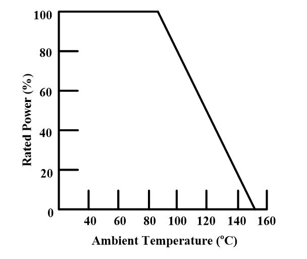
Figure 3. Typical Power-Derating Curve
Resistor Power Rating Key Takeaways
Understanding resistor power rating is critical for ensuring the safe, efficient, and long-term operation of electronic circuits. These ratings define the maximum power a resistor can dissipate without failure, and they guide engineers in choosing the right components based on current, voltage, resistance, and environmental factors. Applications ranging from small-scale consumer electronics to industrial machinery rely on appropriate power rating selection to prevent overheating, material damage, or fire hazards. By considering factors such as physical size, material type, ambient temperature, and cooling mechanisms, designers can enhance circuit reliability and performance. In real-world applications, especially where safety and system integrity are paramount, accounting for proper resistor power ratings is not just good practice—it’s essential engineering.