This guide covers Series LC Circuit phasor diagram, characteristics, and several solved examples along with review questions and answers.
A series LC circuit consists of an inductance and a capacitance connected in series, as shown in Figure 1.
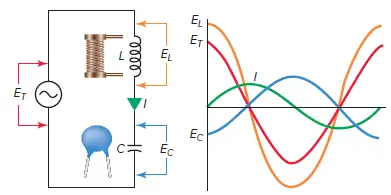
Figure 1 Series LC circuit diagram
 Series LC Circuit Characteristics
The characteristics of an LC series circuit can be summarized as follows:
- It is assumed that there is no resistance in the circuit, only pure inductance and capacitance. As such it is an ideal circuit which only really exists in theory.
- As in all series circuits the current has the same value at all points. This means the current in the inductor is the same as, and therefore in phase with, the current in the capacitor.
- The voltage across the inductor leads the current by 90 degrees, and voltage across capacitor lags the current by 90 degrees.
- Since the current through both is the same, the voltage across the inductor leads the voltage across the capacitor by 180 degrees.
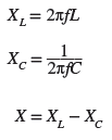
- The voltages dropped across the inductor and the capacitor depend on the circuit current and the values of XL and XC:
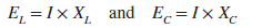
Phasor Diagram for Series LC Circuit
The circuit vector (phasor) diagram for a series LC circuit is shown in Figure 2 and is constructed as follows:
- The vector diagram is drawn starting with a horizontal line representing the current vector I, which is the common quantity.
- The voltage vector, EL, is placed 90 degrees ahead of I since the voltage leads the current by exactly 90 degrees in an inductor.
- The voltage vector, EC, is placed 90 degrees behind that of I since the voltage lags the current by exactly 90 degrees in a capacitor.
- The vector addition of EL and EC gives a resultant that represents the applied voltage ET.
- Since the EL and EC voltages are 180 degrees out-of-phase, the total applied voltage ET is the difference between these two voltage values and is in phase with the larger of the two voltages, which in this case is EL.
- The larger of voltages EL and EC, or their respective reactance values, determines if the circuit is inductive or capacitive.
- Any time XL is greater than XC, the voltage across the inductor will be greater than that across the capacitor, and the circuit will be inductive in nature. The reverse is true whenever XC is greater than XL.
- In this example, the circuit would be inductive.
- Note that either or both of the voltages, EL or EC may be greater than the total applied voltage in an AC series circuit consisting of only L and C.
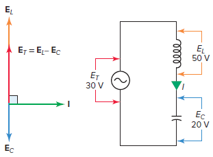
Figure 2 Series LC circuit vector (phasor) diagram.
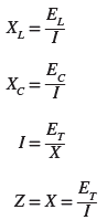
Series LC Circuit Impedance
The series LC circuit voltage vector and reactance vector are similar to each other, except for the units by which they are measured. Both XL and XC are 180 degrees out of phase with each other; therefore, the value of one subtracts from the other, leaving the circuit either inductive or capacitive, depending on which reactance is larger.
The equivalent total reactance (represented by the symbol X) of a series LC circuit is equal to the difference between the values of inductive and capacitive reactance:
The total opposition to the current flow in a series LC circuit is equal to the equivalent total reactance (X). Therefore, the impedance (Z) of the circuit will be the same value as the total equivalent reactance. According to Ohm’s law, the following formulas then apply:
Series LC Circuit Calculations Example 1
For the series LC circuit of Figure 3, determine:
- Equivalent total reactance (X).
- Circuit current flow (I).
- Voltage drop across the inductor (EL).
- Voltage drop across the capacitor (EC).
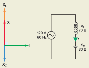
Figure 3 Circuit for example 1.
Solution:
$a.X={{X}_{L}}-{{X}_{C}}=70\Omega -30\Omega =40\Omega $
\[b.I=\frac{{{E}_{T}}}{X}=\frac{120V}{40\Omega }=3A\]
$c.{{E}_{L}}=I\times {{X}_{L}}=3A\times 70\Omega =210V$
$d.{{E}_{C}}=I\times {{X}_{C}}=3A\times 30\Omega =90V$
The total applied voltage ET is always in phase with either EL or EC (whichever is greater), and therefore will always be 90 degrees out of phase with the current. There is a constant interchange of power, or energy, between the source and the circuit, but no power consumption. This means the circuit will react as if it contained only inductance or capacitance. Therefore, for a series LC circuit:
- The applied voltage and current will always be 90 degrees out of phase.
- The true power or watts will always equal zero.
- The power factor will always equal zero.
Example 2
Problem: For the series LC circuit of Figure 4, determine:
- Inductive reactance (XL).
- Capacitive reactance (XC).
- Equivalent total reactance (X).
- Circuit current (I).
- Voltage drop across the inductor (EL).
- Voltage drop across the capacitor (EC).
- Apparent power (VA).
- Reactive power (VARs).
- True power (W).
- Power factor (PF).
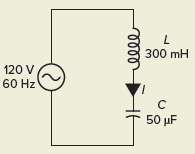
Figure 4 Circuit for example 2.
Solution:
$a.{{X}_{L}}=2\pi fL=2\times 3.14\times 60\times 0.3=113\Omega$
\[b.{{X}_{C}}=\frac{1}{2\pi fC}=\frac{1,000,000}{2\times 3.14\times 60\times 50}=53.1\Omega \]
$c.X={{X}_{L}}-{{X}_{C}}=113-53.1=59.9\Omega $
\[d.I=\frac{{{E}_{T}}}{X}=\frac{120V}{59.9\Omega }=2A\]
$e.{{E}_{L}}=I\times {{X}_{L}}=2A\times 113\Omega =226V$
$f.{{E}_{C}}=I\times {{X}_{C}}=2A\times 53.1\Omega =106V$
$g.VA={{E}_{T}}\times I=120V\times 2A=240VARs$
$h.VARs=VA=240VARs$
\[i.W=0\left( \text{Pure Reactive Load} \right)\]
\[j.PF=\frac{W}{VA}=\frac{0}{240}=0\]
Review Questions
1. For the series LC circuit of Figure 5, determine:
- Equivalent total reactance (X).
- Circuit current flow (I).
- Voltage drop across the inductor (EL)
- Voltage drop across the capacitor (EC)
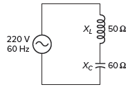
Figure 5 Circuit for review question 1.
2. For the series LC circuit of Figure 6, determine:
- Voltage drop across the inductor.
- Current flow.
- Impedance.
- Apparent power.
- Net reactive power.
- True power.
- Capacitive reactance.
- Phase angle of the circuit.
- Power factor of the circuit.
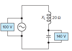
Figure 6 Circuit for review question 2.
Review Questions – Answers
- (a) 10 Ω, (b) 22 A, (c) 1100 V, (d) 1320 V
- (a) 40 V, (b) 2 A, (c) 50Ω, (d) 200 VA, (e) 200 VARs, (f) zero watts, (g) 70 Ω, (h) 90°, (i) zero
Series LC Circuit Key Takeaways
In conclusion, understanding series LC circuits is essential for various applications in electrical and electronic systems. These circuits play a fundamental role in resonant circuits, filters, oscillators, and impedance matching networks, which are widely used in communication systems, power electronics, and signal processing. The ability to analyze their phasor diagrams, impedance, and voltage relationships enables engineers to design efficient circuits that optimize energy transfer and minimize power losses. By mastering these concepts, professionals can develop innovative solutions for modern electrical and electronic applications, ensuring reliable and efficient system performance.