The article discusses low-voltage control circuits using relays for lighting and power circuits, emphasizing their operation and applications in various scenarios. It covers the basics of relay mechanisms, multipoint control systems, indicator light integration, and dual-coil relay systems for remote control, along with examples of their practical implementation in lighting and thermostat control circuits.
Low-voltage control of a lighting and/or power circuit utilizes a relay. The relay has a low-voltage (typically 20 to 28 V), low-current coil, and electrical contacts capable of switching the line voltage and current required by the load. The relay has some form of mechanical latching so that only a pulse of current is required to open or close the relay. The cutaway illustration of a relay in Figure 1 is shown with its contacts closed. It will remain in that condition until another current pulse is received.
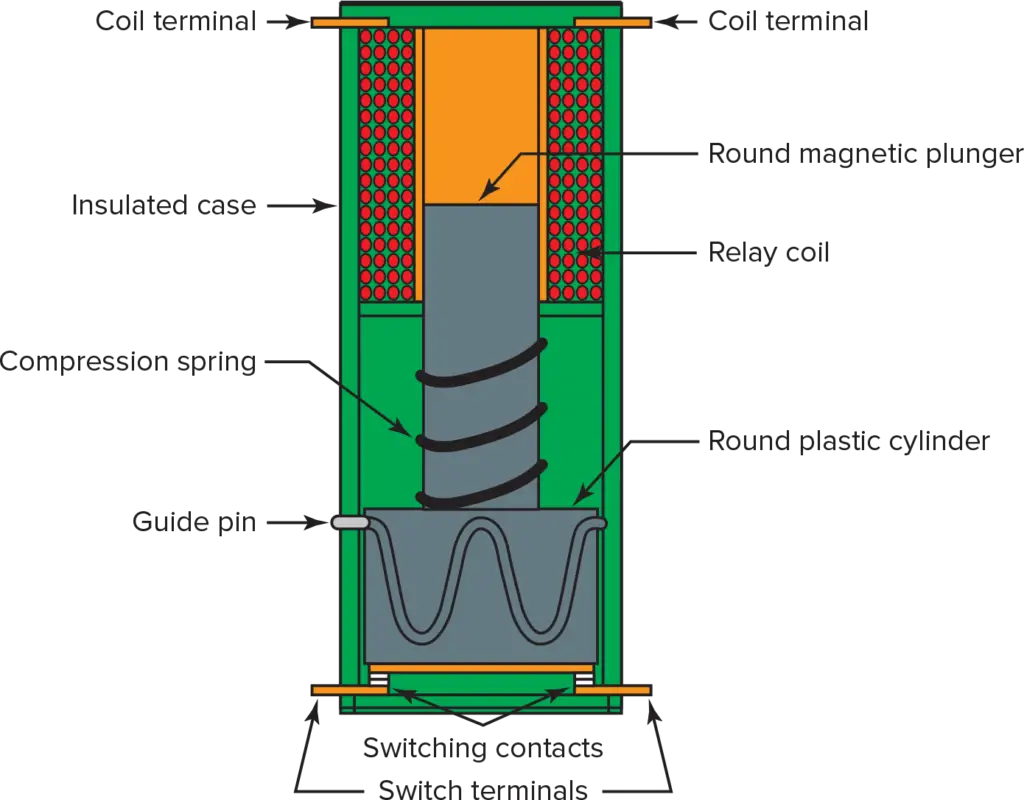
Figure 1. Low-voltage control relay with mechanical latch. Every other current pulse closes the contacts.
When the relay coil in Figure 1 receives a current, it pulls the plunger and the top contacts up and tries to center the plunger in the coil. This opens the contacts. This action also rotates the top contacts and the plastic cylinder about 45° because of the wavy groove on the circumference of the cylinder and the stationary guide pin engaged in the groove. When the coil current stops, the compression spring forces the plunger and cylinder back to the down position. The cylinder rotates another 45° as it is forced down. Now the switch contacts are open because the top contacts and their connecting bar are 90° from (perpendicular to) the bottom contacts and their terminals. The next current pulse will cause the cylinder and the attached contacts to rotate another 90° as they are forced up and down. This, of course, aligns the upper and lower contacts and closes the relay switch.
Low-Voltage Controlled Lighting System
Figure 2 shows how a relay such as the one in Figure 1 is used in a low-voltage controlled lighting system. The relay, along with other relays, is mounted in a relay panel located close to the distribution panel. One branch circuit leading from the distribution panel to the relay panel provides power for many lights. No matter how complex the switching arrangement, the only additional power cable required is a two-conductor (with ground) cable from the relay panel to the light outlet box. All the cable used for switching is low-voltage, light-gage (typically No. 22 to No. 18) cable. The switch is a normally open, momentary-contact, push-button type. The low-voltage supply is a current-controlled type that reduces the relay coil current to a safe value if the push-button switch is held on too long or sticks in the on position.
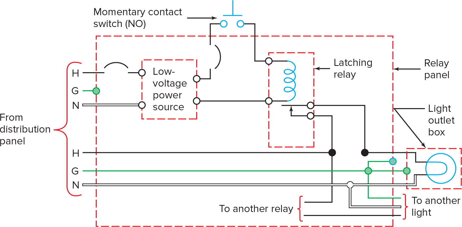
Figure 2. Basic low-voltage controlled lamp circuit. The control circuitry uses a two-conductor low-voltage low-current cable.
Multipoint Control
Multipoint control of a low-voltage controlled light is illustrated in Figure 3. Notice that this figure is a repeat of Figure 2 with the addition of some switches and a two-conductor cable. Since low-voltage cables and switches are relatively cheap, switches may be located in areas quite remote from the controlled light.

Figure 3. Multipoint control of a low-voltage controlled lamp. Two-conductor, low-voltage cable is used between the switches.
With low-voltage controlled systems, it is practical to have a master control panel, with a switch for each relay, located in the master bedroom or other convenient location. This makes it easy to turn off lights in unoccupied rooms. Of course, there can be duplicate master control panels because any number of switches can be wired in parallel.
Remote Switching
Remote switching of a low-voltage controlled light is more convenient when lighted-button switches, which indicate when a light is on, are used. Figure 4 shows how indicator (pilot) lights are added to the low-voltage control circuit. For this circuit, the control relay has another set of contacts. Since the additional contacts switch low currents and voltage, they can be much lighter-duty contacts than those used to switch the load (120-V lamp). The pilot (indicator) lights can be either incandescent lamps or light-emitting diodes (LEDs). The LED light requires less current, but it requires a direct current supply. With lighted switches, a four-conductor cable is required between switches. Also, notice that the pilot light is on when the 120-V lamp is on. This is just the opposite of the lighted-handle switches.
Figure 4. Adding an indicator light to the control switches requires a four-conductor, low-voltage cable in the control circuit.
Another type of latching relay (dual-coil) for low-voltage control is illustrated in Figure 5. It is shown in the on state, with the spring holding the plunger down and the contacts closed. The upper contact is a spring contact, and when given the chance, it springs up and opens the contacts. When the upper coil receives a current pulse, the plunger is pulled up and held up by the compression spring. This allows the upper contact to spring up to the off-state. Operation of this relay requires a three-conductor, low-voltage cable, and an SPDT momentary-contact rocker switch. Figure 6 shows the basic circuit used to control a dual-coil relay and its load.
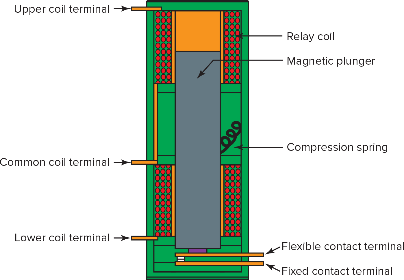
Figure 5. Dual-coil latching relay. The upper coil must be pulsed to open the contacts.
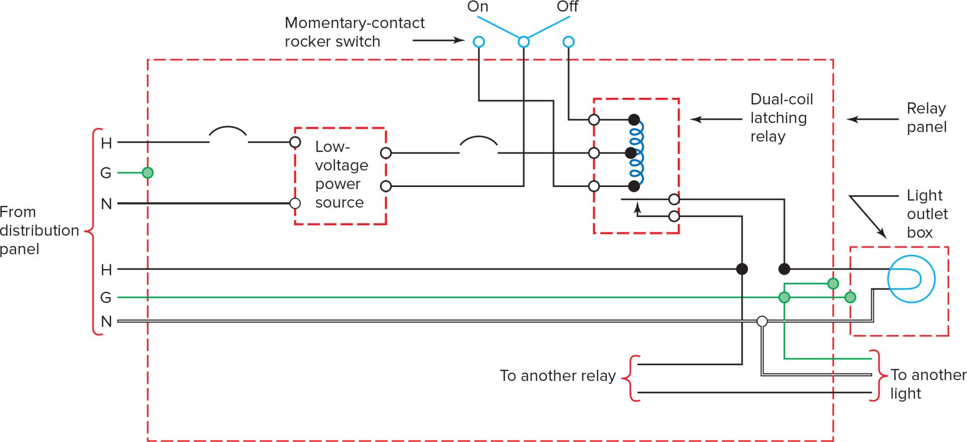
Figure 6. Low-voltage controlled lamp circuit using a dual-coil relay. The control circuitry uses a three-conductor cable.
Multipoint control of the circuit in Figure 6 can be obtained by adding rocker switches in parallel using a three-conductor cable. With this relay, it is not necessary to know the present state (on or off) of the light to control the light from a remote location because this relay requires dedicated pulses for on-and-off action.
Another feature of the dual-coil-relay system is the simplicity of the master control unit. As shown in Figure 7, the unit consists of two push-button switches and one two-pole rotary switch. The rotary switch can have many more positions than shown in Figure 7. To operate the master unit, merely rotate the rotary switch to select the desired light and press the on or off button. To quickly turn all lights on, just hold the on switch down while rotating the rotary switch through all of its positions. Of course, all lights can be turned off just as quickly.

Figure 7. Master control station for a dual-coil relay circuit. The master control uses two NO push-button switches and a 2P rotary switch.
Thermostat Control
Figure 8 shows another type of low-voltage control circuit. This circuit is used to provide remote thermostat control of one or more baseboard electric heaters. Notice that the transformer primary is energized all the time, so the circuit uses a little energy even when the heater is off.
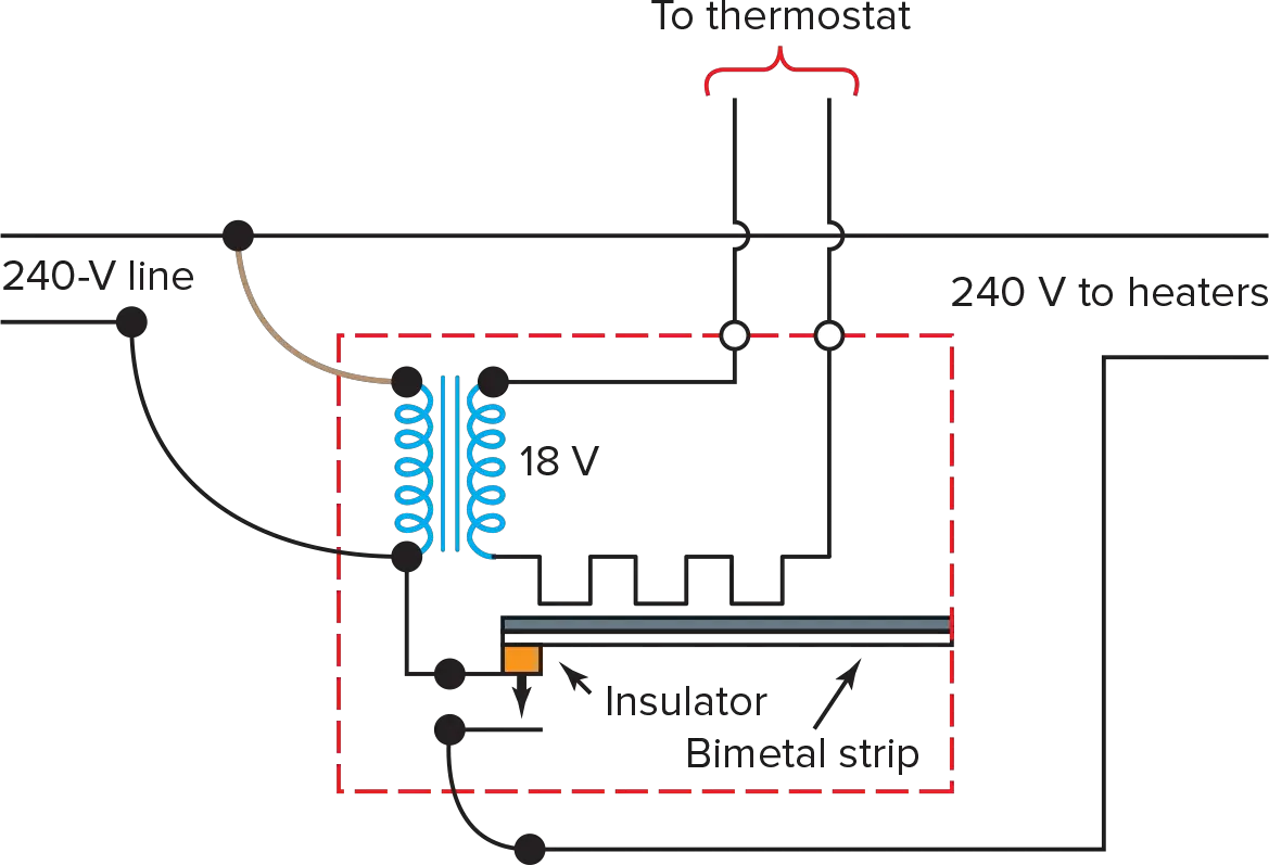
Figure 8. Electric heater control circuit. Note that the required grounding conductors are not shown.
When the thermostat detects the need for heat, its detection device closes a set of contacts. This allows a small (milliampere) current to flow through the small heating element in the 18-V secondary circuit. The heating element heats the bimetal strip and causes it to bend down and close a set of heavy-duty contacts that connect the 240-V main line to the 240-V heater load. After the room warms up, the thermostat contacts open, the bimetal strip cools and straightens out, and the 240-V line is disconnected from the heater.
Low-Voltage Control Circuits Key Takeaways
Low-voltage control circuits, particularly those employing relays, play a vital role in a wide range of applications, from lighting control to thermostat regulation. By utilizing low-voltage, low-current components, and innovative relay mechanisms, these circuits offer efficient and flexible solutions for managing electrical systems. Their ability to provide multipoint control, integrate indicator lights, and facilitate remote operation enhances convenience, energy efficiency, and safety in various settings.