The article provides an overview of inductive and capacitive reactance in AC circuits, explaining how these components influence current and voltage behavior. It also introduces the concept of impedance as a combination of resistance and reactance, essential for analyzing circuits with mixed elements.
Basically, there are three types of elements that may be found in ac circuits. These may be classified as resistive, inductive and capacitive reactance. The value of resistance is independent of frequency, but the value of both an inductive circuit and a capacitive circuit is dependent on voltage frequency.
If a circuit contains only resistive elements, the value of current in an ac circuit can be calculated by the relationship
\[I=\frac{V}{R}\]
where R is the resistance (ohms). In a purely resistive circuit, the current is in phase with the applied voltage.
Figure 1: Phasor Diagram for a Purely Resistive Circuit
If a circuit contains only inductive elements, the value of current can be determined by the relationship
\[I=\frac{V}{\omega L}\]
Where
V is the volts (AC)
ω = 2πf (rads/s)
L is the inductance (H)
In a purely inductive circuit, the current lags the applied voltage by 90° in a V–I phasor diagram.

Figure 2: Phasor Diagram for a Purely Inductive Circuit
If a circuit contains only capacitive elements, the value of current can be determined by the relationship
\[I=V\omega C\]
Where C is the capacitance (F). In a V–I phasor diagram for a purely capacitive circuit, the current leads the applied voltage by 90°.
Figure 3: Phasor Diagram for a Purely Capacitive Circuit
The aforementioned relationships of voltage and current are interesting and of value. It will be found that when computing voltages and currents that have a mix of these elements, the concept of impedance will have a very practical use.
Basically, AC impedance is the complex (not the scalar) ratio of volts to amps in an ac circuit. Impedance represents the ability of an ac circuit to resist the flow of current. Impedance is also the ratio of two phasors, but it is not a phasor. It is a complex number that connects one phasor to another phasor. Expressed as “Z,” impedance may be stated mathematically as
\[\underline{Z}=\frac{\underline{V}}{\underline{I}}\]
NOTE: An underlined variable, as “$\underline{Z}$ ” designates that the variable is a vector quantity and not a scalar quantity. However, the practice of underlining variables to designate a vector quantity is not rigorously followed. In most instances, it is understood that a stated variable is a vector quantity and not necessarily underlined.
Mostly, the underline serves as a reminder that the variable is a vector quantity. A variable that is designated as an absolute value, as |Z|, specifically designates that the variable is a scalar quantity and not to be confused with a vector quantity.
For a purely resistive circuit, ZR = R, where R is the value in ohms of the resistance.
It may also be shown that,
- For a purely inductive circuit, the impedance is \[{{Z}_{L}}=\text{ }j\omega L\]
- For a purely capacitive circuit, the impedance is \[{{Z}_{C}}={}^{1}/{}_{j\omega C}\]
Inductive Reactance Formula
Consider a sinusoidal current to be flowing in the pure inductance as shown in the following Fig. that is
$i={{I}_{m}}\sin \left( wt \right)$

Since the sine wave of current is constantly changing, the coil produces a counter emf given by
${{V}_{L}}=L\frac{di}{dt}$
The voltage across the inductor is proportional to the slope of the sine wave of current and is the, therefore, a cosine wave, as shown in Fig.
Thus, in the purely inductive circuit, the current lags the voltage by a phase angle of 90°. Now substituting the equation for current into the equation for inductor voltage, we find that
\[{{V}_{L}}=L\frac{di}{dt}=L\frac{d\left( {{I}_{m}}sinwt \right)}{dt}={{I}_{m}}wL\cos \left( wt \right)\]
The quantity ImωL is the maximum value of the voltage across the inductor (it occurs at t=0)
\[\begin{matrix} {{V}_{m}}={{\operatorname{I}}_{m}}\omega L & {} & \left( 1 \right) \\\end{matrix}\]
The quantity ωL is called an inductive reactance and is a measure of opposition to alternating current. Inductive reactance is measured in Ohm. The symbol XL is used to denote inductive reactance.
${{X}_{L}}=wL=2\pi fL$
Since the maximum values of equation (1) are related to effective values, so we can write
${{V}_{L}}={{I}_{L}}{{X}_{L}}$
The pure inductance cannot dissipate any power. Rather, the inductance stores and releases energy in the form of magnetic field. The inductive reactive power equals the product VLIL.
${{Q}_{L}}={{I}_{L}}{{V}_{L}}=I_{L}^{2}{{X}_{L}}$
Example of Inductive Reactance
The voltage across a 1 H inductor is e=10sin200t. what is the expression of an instantaneous current?
Solution
${{X}_{L}}=\omega L=200*1=200~\Omega $
${{I}_{m}}=\frac{{{V}_{m}}}{{{X}_{L}}}=\frac{10}{200}=0.05~A$
In the inductance, I lags e by 90 degree, so we can write an expression for an instantaneous current as:
$i={{I}_{m}}\sin \left( wt-{{90}^{{}^\circ }} \right)=0.05~\text{sin}\left( 200t-{{90}^{{}^\circ }} \right)$
- You May Also Read: Inductive Reactance in Detail
Capacitive Reactance Formula
Consider a pure capacitor connected to a sinusoidal AC voltage as in the following figure.
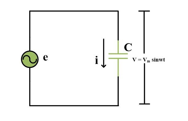
The voltage across the capacitor is
$v={{V}_{m}}\sin \left( wt \right)$
While instantaneous current flowing to a capacitor is
\[i=C\frac{dV}{dt}\]
This above expression indicates that current is proportional to the slope of the voltage curve. In this case, the current is proportional to the slope of a sine wave. In fact, the slope of a sine wave is a cosine wave as shown in Fig. Hence in the pure capacitive circuit, the current leads the voltage by an angle of 90°.
Now substituting the sine wave expression for voltage into the current equation. We obtain
\[i=C\frac{d\left( {{V}_{m}}\sin \left( wt \right) \right)}{dt}=wC{{V}_{m}}\cos \left( wt \right)\]
$i=wC{{V}_{m}}\cos \left( wt \right)~~~~~\text{ }\cdots \text{ }~~\left( 2 \right)$
From equation (2) one finds maximum current to be;
\[\begin{matrix} {{\operatorname{I}}_{m}}=\omega C{{V}_{m}} & {} & at\text{ }t=0 \\\end{matrix}\]
Or
\[\frac{{{V}_{m}}}{{{I}_{m}}}=\frac{1}{wC}\]
The quantity 1/ωC is called the capacitive reactance, measured in ohm and represented by Xc.
\[{{X}_{C}}=\frac{1}{wC}=\frac{1}{2\pi fC}\]
Remembering that the effective values are related to the maximum values by the same ratio, so we can write
${{V}_{C}}={{I}_{C}}{{X}_{C}}$
The pure capacitance cannot dissipate any power. Rather, capacitance stores or releases energy in the form of the electric field. The capacitive reactive power equals the product VCIC.
${{Q}_{C}}={{I}_{C}}{{V}_{C}}=I_{C}^{2}{{X}_{C}}$
Example of capacitive reactance
In above capacitor circuit, C=2μF and the source supply 1 kHz at an effective or RMS value of 10 V. (a) what current flows?
(b) What is the reactive power?
Solution:
(a):
\[{{X}_{C}}=\frac{1}{\omega C}=\frac{1}{2*\pi *f*2*{{10}^{-6}}}=79.5~\Omega \]
${{I}_{C}}=\frac{{{V}_{C}}}{{{X}_{C}}}=\frac{10}{79.5}=0.126~A$
(b):
${{Q}_{C}}={{V}_{C}}{{I}_{C}}=10*0.126=1.26~vars$
Combined Resistance and Reactance
In practice, most circuits contain a mix of resistive components along with reactive components that could be inductive or capacitive. In order to analyze these types of circuits, the use of impedance proves to be an especially helpful tool. As stated before, the impedance of a circuit, regardless of the nature of the components, can be described by the relationship
\[Z=\frac{V}{I}\]

Figure 8: Impedance Diagram
In a circuit that contains both resistive and reactive elements, the impedance in the complex plane can be described by the general relationship depicted in Figure 8, where, in the rectangular form,
\[Z=R+jX\]
R is the resistive component of impedance (ohms)
X is the reactive component of impedance (ohms)
- You May Also Read: Capacitive Reactance in Detail
Inductive and Capacitive Reactance Key Takeaways
Understanding inductive and capacitive reactance is essential in analyzing and designing AC circuits, especially those containing a combination of resistive, inductive, and capacitive elements. These concepts explain how different components behave with changing frequency, influencing current flow and phase relationships between voltage and current. The introduction of impedance as a complex quantity allows engineers and technicians to calculate and manage AC circuit performance more effectively, especially in real-world applications like power distribution, signal processing, communication systems, and electronics design.