The article discusses the factors affecting capacitance, including dielectric constant, plate area, and plate distance, and explains the unit of capacitance (Farad) along with related calculations. It also provides examples and formulas to illustrate how these factors determine a capacitor’s ability to store charge.
There are three main factors (Dielectric Constant of the material, Area of the plates, and Distance between the plates) affecting the capacitance of the capacitors that will be discussed in this tutorial in detail.
The SI unit of capacitance is the Farad, named in honor of the English physicist and chemist Michael Faraday. The unit symbol for the farad is F. Capacitance is the ability of a component to hold a charge. The amount of charge Q that is stored is proportional to the applied voltage. The charge is also determined by the capacitance of the capacitor. The relationship of these terms can be expressed as follows:
$Q=CV$
Where
Q= electric charge to be measured in coulombs
C= capacitance in Farads
V= electric potential across the capacitor in volts
In terms of direct current, this equation may be stated as follows:
A capacitor has the capacity of one farad if one volt applied across the plates produces a charge of one coulomb in the capacitor.
- You May Also Read: Capacitive Reactance
Example
A 0.05 F capacitor has 15 V DC applied across its plates. What is its charge in coulombs?
Solution
$Q=CV=0.05*15=0.75\text{ C}$
Example
What is the capacitance of a capacitor that receives a charge of 0.001 C when 200 V is applied?
Solution
$C=\frac{Q}{V}=\frac{10*{{10}^{-4}}}{2*{{10}^{2}}}=5*{{10}^{-6}}\text{ F}$
The unit of capacitance may also be described in terms of an alternating current (one that is constantly changing). If V changes at the rate of one volt per second and causes one coulomb of charge per second to flow, the capacitance is one farad. Since 1 C/s is 1 A, we may say that the capacitance of the device is one farad if one ampere flows through the circuit when the applied emf is changing at the rate of one volt per second.
The farad is an extremely large unit of capacitance. In practice, it is more convenient to use a small unit of farad such as microfarad (μF), which is 1*10-6. In fact, for very high-frequency applications, the nano farad (nF) and the picofarad (pF) are more frequently used. These units are 1*10-9 F and 1*10-12 F, respectively.
Example
A certain capacitor is rated at 0.0068 F. What is the capacity in micro-Farad and in nano-Farad?
Solution
One farad equals 1*106 μF. Therefore,
$0.0068\text{ F * 1}{{\text{0}}^{\text{6}}}=6800\text{ }\mu \text{F}$
There are 103 nF in 1 μF. Therefore,
$06800\text{ }\mu \text{F*1}{{\text{0}}^{\text{3}}}=6,800,000\text{ nF}$
Dielectric Constant (k)
The ratio of the capacitance of a capacitor with a given dielectric to the capacitance of an otherwise identical capacitor having air or vacuum for its dielectric.
One of the principal factors affecting the capacitance of a capacitor is the type of dielectric material used between plates. These materials, insulators, are rated by their ability to produce dielectric flux in terms of a parameter called dielectric constant (k). Materials having a high dielectric constant can create more capacitance than ones with a low k for the same plate area and separation.
A standard is necessary for comparing the dielectric constant of one material to another. A vacuum serves as this standard and is assigned a value of unity. Air has essentially the same value. The dielectric constant of all materials is compared with that of a vacuum. Thus, if a particular dielectric material has a k value of 6.5, it will produce 6.5 times more capacity than if a vacuum were used in the same-size capacitor. The dielectric strength of a number of materials is given in Table 1.
Material Dielectric Constant k
Air or Vacuum 1
Paper 2.0-6.0
Plastic 2.1-6.0
Mineral Oil 2.2-2.3
Polystyrene 2.6
Silicon Oil 2.7-2.8
Quartz 3.8-4.4
Glass 4.8-8.0
Porcelain 5.1-5.9
Mica 5.4-8.7
Askarel Oil 5.6-5.9
Aluminum oxide 8.4
Tantalum pentoxide 26
Ceramic 12-400,000
Table 1: Dielectric Constants
Factors Affecting Capacitance
Several factors affect the ability of a capacitor to store an electric charge. They are as follows:
- The area of the plates
- The distance between the plates
- The dielectric constant of the material between plates
The relationship of these parameters can be understood by reference to the elemental parallel-plate capacitor illustrated in Figure 1.
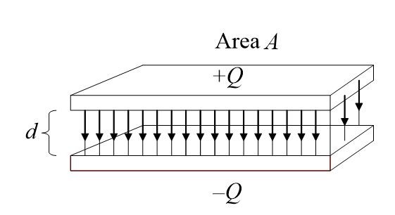
Figure 1. Parallel-Plate Capacitor
The following formula also expresses the relationship:
$C=0.224\frac{kA}{d}$
Where
K = Dielectric constant of the material between the plates
A = Area of one plate in square inches
D = Distance between plates in inches
0.224 = conversion factor when using inches
When the dimensions are in centimeters (cm), use the following formula:
$C=0.08842\frac{kA}{d}$
Where
K=dielectric constant of the material between the plates
A= area of one plate in square cm
D = distance between plates in cm
0.224 = conversion factor when using centimeters
An examination of these formulas indicates that the capacitance varies directly with plate area and inversely with the spacing between plates. The dielectric constant also directly affects the capacitance. For example, if mica is substituted for air as the dielectric, the capacitance will increase from 5.4 to 8.7 times.
If the capacitor is composed of more than two parallel plates, its capacitance in picofarads is calculated by the following formula:
$C=0.08842\frac{kA}{d}(n-1)$
Where n is the number of plates.
Example
A simple capacitor has two parallel plates separated by 2 cm. If the area of one plate is 100 cm2 and the dialectic is polystyrene, what is the capacitance in picofarads?
Solution
$C=0.08842*\frac{2.6*100}{2}=11.49\text{ pF}$
In the above solution, 2.6 is the dielectric constant of polystyrene given in Table 1.
Factors Affecting Capacitance Key Takeaways
Understanding the factors affecting capacitance—namely the dielectric constant, plate area, and distance between the plates—is essential in the design and application of capacitors in real-world electrical and electronic systems. These parameters directly influence how much electric charge a capacitor can store, which is critical in circuits for energy storage, signal processing, filtering, and timing applications. The ability to calculate capacitance using standard formulas ensures precise control over circuit behavior, while knowledge of appropriate units—from farads to microfarads and beyond—ensures compatibility in both low-frequency and high-frequency applications.