The article provides an overview of various network cable types, connectors, and Ethernet standards, along with their characteristics and typical uses. It also covers the components and structure of wiring distribution systems used in both home and enterprise networks.
Lesson Objectives
By the end of this lesson, you will be able to:
- Categorize standard media types and connectors.
- Identify components of wiring distribution.
- Compare and contrast different Local Area Network (LAN) technologies.
- Troubleshoot common physical connectivity problems.
Network Media
When data packets leave the NIC also known as a network interface card, the medium that takes the packet from source to destination is called media. Once the media access method, Carrier Sense Multiple Access/Collision Detection (CSMA/CD) or Carrier Sense Multiple Access/Collision Avoidance (CSMA/CA), has been implemented, the data packets are placed on the media and sent to the final destination. Media can have various forms including copper wire, fiber optics, and wireless.
Copper Wire
A copper wire connection is the most commonly used media. Copper wire media comes in two forms. Coaxial can be ThinNet (Figure 1) or ThickNet (Figure 2). Twisted cable types (Figure 3) include unshielded twisted pair (UTP), shielded twisted pair (STP), and CATx.
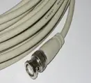
Figure 1 ThinNet |
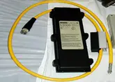
Figure 2 ThickNet |
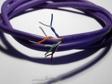
Figure 3 Twisted-pair copper wire |
Ethernet
Ethernet allows network communication to occur over a copper wire or cable and it carries the IEEE 802.3 standard. Older Ethernet standards typically seen in BUS topologies include ThinNet and ThickNet. Unshielded Twisted Pair (UTP) and Shielded Twisted Pair (STP) are typically found in more advanced topologies. Review the chart for additional information on ThinNet and ThickNet.
| Network | Coax Grade | Max Distance | Resistance |
| ThinNet | RG-58 | 185 | 50 ohms |
| ThickNet | RG-8 or RG-11 | 500 | 50 ohms |
ThinNet (RG-58) is used for short distance Ethernet communication and supports up to 30 connected nodes and system speeds of 10 Mbps. When ThinNet is used the nodes have to be spaced at least 0.5 meters from each other. A ThinNet network connects nodes via British Naval Connectors (BNC) (Figure 4) and T- connectors (Figure 5).
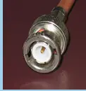
Figure 4 BNC Connector |
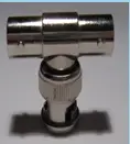
Figure 5 T-Connector |
ThickNet (RG-8/RG-11) is used for long distance Ethernet communication and supports up to 100 connected modes and system speeds of 10 Mbps. Nodes in ThickNet have to be spaced exactly 2.5 meters from each other. A ThickNet network connects nodes via a Transceiver (Figure 6) that taps into the cable. The terminating end has an N – connector (Figure 7).
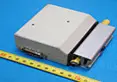
Figure 6 Transceiver |

Figure 7 N Connector |
In addition to the end connectors mentioned for ThinNet and ThickNet Ethernet connections there are a few other connectors and components used to attach cables and wiring to different Ethernet connections. F-connectors (Figure 8) are coaxial connectors commonly used in cable and satellite television. Vampire taps (Figure 9) are used to connect network nodes to cables.

Figure 8 F-Connector |
Figure 9 Vampire Tap |
Unshielded Twisted Pair (UTP)/Shielded Twisted Pair (STP)
UTP describes two pair of copper wire being twisted together. The number of pairs depends on the communication type. STP describes where the copper wire pairs are shielded for Electromagnetic Interface (EMI).
EMI disrupts, alters, and blocks communication from taking place over the media. EMI can be caused by various sources, for example TV signals, cell phone signal, EMI for electric motors, power lines, or any other high strength electrical transmission.
Coaxial (Bus) communications use connectors to attach to networks as do UTP and STP cabling. There are two common connectors used with UTP and STP cabling.
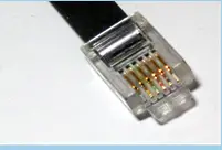
RJ-11 is commonly used in telephone communication and has six pins. |
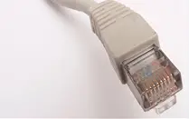
RJ-45 is commonly used in computer and network communication and has eight pins. |
There are many different locations where cable is run for organizations and depending on the job and location of the cables within the building, various cable types are used. Plenum is the area between the ceiling and suspended tiles as well as between the bottom of an office building floor (non-ground floor) and crawl space. It is important to be aware of the following:
- Plenum cables are made from a plastic that in event of a fire would produce a lower toxic emission.
- Plenum cables are usually more rigid than normal UTP/STP cables.
Review the following chart for the UTP category and data rates associated with different usage application types. All UTP categories have a 100 m distance limit and CAT 7 is the proposed standard.
| Category | Data Rate | Typical Use |
| CAT 1 | 1 Mbps | Voice Only |
| CAT 2 | 4 Mbps | Token Ring |
| CAT 3 | 10 Mbps | Ethernet |
| CAT 4 | 16 Mbps | Token Ring |
| CAT 5 | 100 Mbps | Ethernet |
| CAT 5e | 1000 Mbps (1 Gbps) | Ethernet |
| CAT 6 | 10 Gbps | Ethernet |
| CAT 7 | 10 Gbps | Ethernet |
Ethernet Cables
There are multiple types of Ethernet cables used to send and receive data over wire pairs 1, 2, 3, and 6. Patch cables are used to connect hosts to each other as well as the network. Straight-through cables use four wire pairs that align to the same pins on each side of the wire. Crossover cables take the transmitting signal and pairs it with the receive pins. A T1 crossover is used to transmit data between two clients with a Channel Service Unit/Data Service Unit (CSU/DSU).
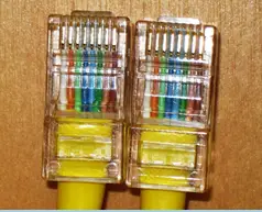
Figure 12 Straight-through cable |
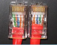
Figure 13 Crossover cable |
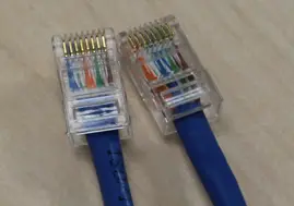
Figure 14 T1 Crossover cable |
A CSU/DSU is a hardware device about the size of an external modem that converts digital data frames from the communications technology used on a local area network (LAN) into frames appropriate to a wide-area network (WAN) and vice versa. An example of how a CSU/DSU works would be when someone hosts a Web business from his or her home and have leased a digital line (perhaps a T-1 or fractional T-1 line) from a phone company/ISP. On both ends of communication (ISP gateway and the person’s home POP) there will be a CSU/DSU to convert signals.
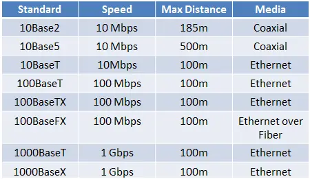
It is important to be aware that there are also Ethernet standards which define the type of media used as well as the speed and the distance limitations. IEEE 802.3ab and IEEE 802.3z are standards for 1Gbps data rates. See the chart for details. Note: ‘Base’ stands for Baseband frequencies. Baseband is 0 to Max.
Wire Distribution
Copper wire cabling technology has advanced since the use of ThinNet and ThickNet. Copper wire cabling is used to interconnect computers and network devices.
How does data sent via the copper wire media traverse our internal network and when needed access the internet?
- A typical path data takes on a corporate network includes patch cable, a wall plate, patch panel, switch, Intermediate Data Frame (IDF), Main Data Frame (MDF), and a Demarc.
- On a home network the path can have fewer parts. More than likely there is a host (PC, laptop, etc.) and there may or may not be wired connections. Whether wired or wireless the host connects to a router provided by their ISP to access the internet.
Patch Cables
The patch cable has two wiring standards. Neither standard has a performance advantage over the other. The standard must be maintained throughout the network. Figures 15 (T568A) and 16 (T568B) are two wiring diagrams each with eight wires that are based on four colors: blue, orange, green and brown. For additional information read, What’s the Difference between T568A and T568B?
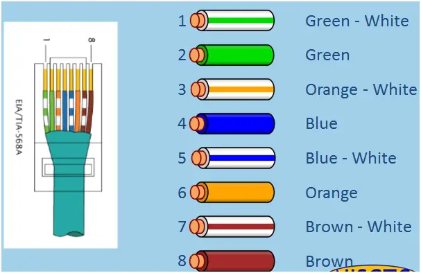
Figure 15 T568A |
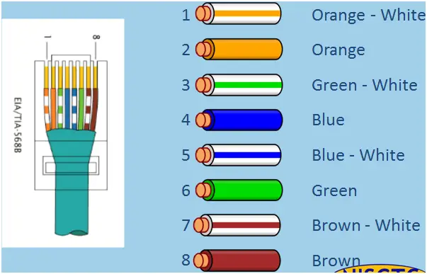
Figure 16 T568B |
Wall Plate
A wall plate (Figure 17) is housing for a RJ-45 jack. The patch cable plug (RJ-45) connects to the wall plate.
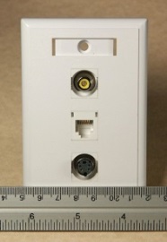
Figure 17 Wall Plate
Patch Panel
The Patch Panel interconnects devices within a LAN. The path from the patch panel to the jack in the wall is commonly referred to as a ‘drop.’ The ‘drop’ from the patch panel to the wall plate typically comes from the ceiling down. Review Figures 19 – 21.

Figure 19 image shows the 110 punch down block (in white). The 110 punch down block is used to secure wires to the patch panel.

Figure 20 This is an image of the back side of the patch panel which is where the patch cable from the RJ-45 jack in the wall terminates (ends).

Figure 21 The is an image of the front side of the patch panel which connects to the front of the switch through patch cables.
Intermediate Data Frame (IDF)
An IDF is used to connect and manage workstations within a certain scope or area on the network. For example, there may be an IDF on each floor of a 10 story office building. An IDF could also represent an area with many workstations such as a computer lab. IDF is also referred to a horizontal cabling or horizontal cross–connect (HCC) cabling.
Main Data Frame (MDF)
A MDF (Figure 22) is used to connect to the Telco or ISP. It is the central telecommunication distribution point within a building. MDF is also referred to as the Vertical cross – connect (VCC) cabling.
MDF’s supply the network connection through cross-connects to the IDFs. A cross connect is where you take multiple cables and connect them to other cables or equipment such as an IDF.

Figure 22 Main Data Frame
The MDF is considered to be Customer Premise Equipment (CPE). MDFs typically use more equipment including multiple routers and switches whereas an IDF will typically have a patch panel and one or two switches.
Demarc
The ‘Demarc’ or Demarcation point is where the Telco or ISP communications link meets the internal network of a facility. Demarc is also called Point of Presence (POP). The demarcation point is a point where responsibility changes from the service provider to the Internal Network Admin team.
A Demarc extension provides a way to connect the service provider side of the communication link to the customer’s when there is separation between the two points.
Channel Service Unit/Data Service Unit (CSU/DSU) is required by communications carriers to translate data via a hardware data interface. It provides data management before data is sent out from the demarc point. CSU/DSU provides framing for the data, maintains data flow, network performance data, and line management.
A smart jack is a type of demarcation point that separates the carrier wiring from the customer’s. Smart jacks have logic built inside of them to help manage advanced communication links such as a T1. They can convert code and protocols and act as a repeater for weak or degraded signal.
Network Cable Types and Connectors Key Takeaways
Understanding the different types of network cable, connectors, and Ethernet standards—as well as the structure of wiring distribution systems—is crucial for building and maintaining efficient, reliable networks. These components play a vital role in ensuring smooth communication within local area networks (LANs) and in enabling connectivity to the broader internet. In both residential and enterprise environments, the correct selection and configuration of media types like UTP, STP, and coaxial cables, along with proper use of patch panels, wall plates, and distribution frames (IDF and MDF), directly impacts network performance, data speed, and scalability. Additionally, recognizing the significance of standards and troubleshooting physical connectivity issues are essential skills for IT professionals to maintain optimal network functionality.