The article provides an overview of host-to-host communication in computer networks, covering how internal and external data transmission occurs through components like the NIC, MAC address, and IP address. It also explains media access methods, data packet structure, IP addressing types and classes, and the roles these elements play in ensuring proper network communication.
Lesson Objectives
By the end of this lesson, you will be able to:
- Describe how networked systems communicate.
- Explain the relationship between the Network Interface Card, MAC address and IP address.
- Define and identify collisions and media access methods.
- Describe the different components of a data packet.
- Describe and identify the different IP Address ranges, classes and features.
What is Host Communication?
Host communication takes place through circuits in the mother board. Internal host communication on a computer or server will take place through a bus. A bus is a method or framework of transferring data between internal computer components including mother board, memory, hard drives, etc.
Operating Systems
Operating Systems allow the internal components of a host to work together. Without an Operating System host components will not communicate. There are several versions of Operating Systems. The most common versions include: Windows OS, MAC OS X, Unix, Linux, Novell, Cisco IOS, JUNOS, BIOS, etc.
Some Operating Systems are specialized to work with networking equipment such as routers and switches. They are referred to as Network Operating Systems (NOS).
Think About
How does the media connect to the host and vice versa?
- Hosts connect to the network through media. You can think of the Network Interface as the middle man, bringing two sides together like a facilitator.
How does the data pass from the host to the NIC which then forwards data to the media?
- The NIC takes data from the BUS and puts it out onto the media/network.
NIC
The NIC puts data onto the network and receives network data for a host. Two of the more common configurations for a NIC are full duplex and half duplex. Full duplex means data can be sent and received from interface at the same time. Half duplex means data is either sent or received at one time.
Example of NICs
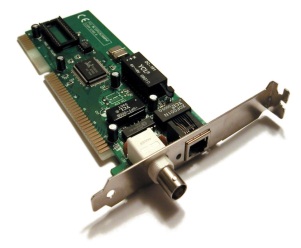 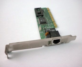
Figure 1 Bonding or port trucking is used to create more bandwidth by bringing together two NIC’s, modems, etc. |
MAC Address
Each NIC has a MAC address (IEEE EUI-48 IPV4 and EUI-64 IPV6). Each MAC address is composed of 48 bit binary numbers, which are displayed in 12 hexadecimal digits (base 16). (i.e. 00:12:3F:29:56:71)
The first six digits (24 bits) represent the manufacture of the device for instance Cisco, Intel, or Dell. The second six digits (24 bits) uniquely identify each NIC and are set by the vendor. An example has been provided.
Example: MAC to Binary
0000|0000|0001|0010|0011|1111|0010|1001|0101|0110|0111|0001
The NIC and the MAC function at layer two (Data Link layer) of the OSI model. This Data Link layer consists of an upper and lower layer.
Upper Layer: The upper layer is called Logical Link Control (LLC). The LLC is responsible for multiplexing (i.e. flow control) and error correction.
Lower Layer: The lower layer is called the Media Access Control (MAC) layer. This layer ensures that the unique MAC address is placed in the transmitted data packet. The MAC layer is responsible for addressing and also determines the media access method.
Media Access Methods
Two of the most common methods to place data on the media are Carrier Sense Multiple Access and Collision Detection (CSMA/CD) and Carrier Sense Multiple Access Collision Avoidance and Collision Avoidance (CSMA/CA).
The CSMA/CD method means that all host/nodes on an Ethernet network “listen” on the media to determine if any other host/node is transmitting data. If the line/media is clear they transmit their data. If the line/media is not clear, they wait unit the media is free to transmit. CSMA/CD is the media access method associated with Ethernet (IEEE 802.3). Access to the media is based on a first come, first serve basis.
The CSMA/CA method is associated with wireless communication (IEEE 802.11). This method also “listens” to the media/radio spectrum; however there are differences associated with this method.
- Random Back off Time: All hosts/nodes will not try to access the media at the same time (when the line is free) a “wait time” is established from the point in which the host is attempting to place data on a busy media.
- Reserving the Media: When a host is ready to transmit, it sends out data to reserve the line. Once it has reserved the line, the host transmits its data.
Why do we need Media Access Methods such as CSMA/CD and CSMA/CA? Think about two trains wanting to access the same track, which one should be allowed access? If both are allowed access to the track and are travelling towards one another, a collision will most likely occur.
A collision occurs when two hosts access the media at the same time and transmit data. A data collision occurs when data becomes corrupt or does not arrive at its destination. When a host detects a collision it will stop transmitting and try again at a later time. If after 16 retries the host still cannot transmit data, it will not continue.
Data Frame
It is important to know the primary format used to send data across a network. The data frame ‘Length’ determines what data type is being used which is an aspect of the transport layer (4) in the OSI Model. For the purposes of the CompTIA Network + exam; The Data Frame is described in layer two. The Data Packet is described in Layer three.
The Data Packet is the primary method. It consists of a frame of eight pieces of information.
- Preamble is a string of zero’s and one’s used to synchronize multiple frames.
- Start of the Frame is a binary sequence that identifies the start of the frame.
- Destination MAC is the MAC address of the host receiving the data packet.
- Source MAC is the MAC address of the host sending the data packet.
- Length provides the number of bytes in the data field.
- Data is the actual data intended to be sent and received.
- Pad – this section adds bytes to packet if under the minimum requirement of 46 bytes.
- Frame error checking – Cyclic Redundancy Check (CRC).

Figure 2 Data Frame and Data Packet are often used interchangeably. The Data Frame provides structure for the Data Packet.
Quick Review
A discussion started about what makes up a network starting with the host.
You learned how the host communicates internally (BUS) and how it communicates externally (Network Interface Controller, NIC). The addressing involved at the host level (Layer 2 – Data Link) was discussed. Now that you have gained an understanding of what components comprise a network the following section will discuss concepts relating to how data leaves the Network Interface to be routed to its destination.
NIC/MAC/IP Relationship
Each NIC has a MAC Address. NIC and MAC processes happen at layer two of the OSI Model. Since data is typically sent between various network segments, there needs to be a way to locate the network segment and host that the data is meant for. If all hosts were on the same network segment (BUS) then MAC addresses may be sufficient for data communication. However, a host can be located in a different office, building, state, or country. It is an Address Resolution Protocol (ARP) that is responsible for converting an IP Address to a MAC address for final delivery of data. The MAC address and the IP address are associated with one another, so data can flow in between network segments.
IP addresses are described in layer three, transport, of the OSI Model. IP addresses are divided into two parts the Network ID and the Host ID. The Network ID identifies the network a host is located on while the Host ID identifies the actual host.
IP addresses come in two versions IPv4 and IPv6. IP addresses can be described as either public or private IP addresses. IP addresses also have five classes or ranges. The reason there are two versions of IP addresses is because the public address space (how many possible addresses) for IPv4 have run out in many areas.
- IPv4 is 32 bit dotted quad notation
- (i.e. 10.23.56.144)
- IPv6 is 128 bit hexadecimal notation
- (i.e. fe80:140b:5771:hb18:bd22:1144:v57r:1234).
- IPV6 is case sensitive.
Public addresses are those which are routable on the internet (outside of internal network). When you go to www.google.com, you are going to a public IP address.
- Class A: 0.0.0.0 – 127.255.255.255
- Class B: 128.0.0.0 – 191.255.255.255
- Class C: 192.0.0.0 – 223.255.255.255
- Class D: 224.0.0.0 – 239.255.255.255
- Class E: 240.0.0.0 – 254.255.255.255
Private addresses are those which are routable only on internal networks. Automatic Private IP Addressing (APIPA) – are IP addresses that a host/system assigns to itself. These IP addresses are not valid on the internet/World Wide Web (www). Furthermore, these addresses are blocked by Internet Service Providers (ISP).
The Internet Assigned Numbers Authority (IANA) is an organization that oversees global IP address Allocation. The IANA is only responsible for allocating the public IP addresses. The American Registry for Internet Numbers (ARIN) assigns IP address space to Internet Service Providers (ISP’s). Some examples of ISP’s include ATT, Verizon, Net Zero, Time Warner, and X/O Communications.
- Class A addresses are routable on the internet with the exception of the “private address” range of 10.0.0.0 – 10.255.255.255. Class A addresses have 8 bits for the network ID and 24 bits for the Host ID’s. The range 127.x.x.x is not used on the internet. Note: The loopback address is within the Class A range. This range is used to test internal host communication. This address is commonly referred to as the loopback address and used to test internal host communication. (IPv6 loopback is ::1.).
- Class B addresses are routable on the internet with the exception of the “private address” range of 172.16.0.0 – 172.31.255.255. Class B addresses utilizes 16 bits for the network ID and 16 bits for the Host ID’s. Note: The private and loopback addresses within the Class B range. IPv6 loopback is ::1. This range is used to test internal host communication. This address is commonly referred to as the loopback address.
- Class C addresses are routable on the internet with the exception of the “private address” range of 192.168.0.0 – 192.168.255.255. Class B addresses have 24 bits for the network ID and 8 bits for the Host ID’s.
- Class D is reserved for multicasting. Multicasting is used to send data to a group of computers on a network. Multicast is a one to many function and takes place at layer two, data link, of the OSI Model.
- Class E is used for experimental purposes only.
Host to Host Communication Key Takeaways
Understanding host-to-host communication is crucial for building and maintaining reliable computer networks. Each element—from the internal communication bus and the role of the NIC, to the unique MAC and IP addresses—plays an essential part in enabling devices to send and receive data accurately. Media access methods like CSMA/CD and CSMA/CA help prevent data collisions, ensuring smooth data transmission across wired and wireless networks. The structure of data packets and frames, along with proper IP addressing and class identification, ensures that information reaches the correct destination efficiently and securely. These concepts are not only foundational for IT professionals but are also vital in real-world applications like internet browsing, email communication, online gaming, cloud computing, and enterprise networking.