The article covers the construction and operation of synchronous machine, focusing on the rotor and stator components. It explains the use of electromagnets to create the field in synchronous machines, comparing salient-pole and round-rotor designs. Furthermore, it highlights the concept of synchronous speed and its relationship to the number of poles and electrical frequency.
In the AC Machine article, we examined a simple permanent-magnet AC machine. That machine used a rotating armature coil, which means the power to run the motor or the power from the generator must be transmitted through the brushes and slip rings. For large machines, that is not very efficient, so AC synchronous machines are built with the armature on the stator and the field on the rotor.
Construction of Synchronous Machine
Rotor
Figure 1 is a sketch of the rotor and stator of a synchronous machine. The rotor would be placed inside the stator.
Instead of a permanent magnet, this machine (as do the overwhelming majority of synchronous machines) uses an electromagnet to create the field. A DC voltage is applied to the coils on the rotor, creating north and south poles. This particular rotor is called a salient-pole rotor because the rotor is not symmetric. In particular, the air gap between the pole faces and the stator is much smaller than that between the sides of the rotor and the stator.
Some machines are built with a round rotor, which has slots in the side to hold the field coils. These are referred to as round-rotor synchronous machines. Round-rotor designs are typically limited to a maximum of four poles, whereas salient-pole machines have been built with over 50 poles. In either case, the rotor only sees a DC flux, so the rotor does not have to be laminated.

Figure 1. Synchronous machine components labeled diagram
Figure 2 shows a salient-pole rotor. This rotor is actually part of the excitation system for a very large (345 MVA) synchronous machine that was disassembled for maintenance. It operates on the same shaft as the larger unit, which is why the shaft diameter is so large.
The front pole-face is marked “stator,” indicating the direction it faces when reassembled. The field coils are located directly behind the pole-faces.
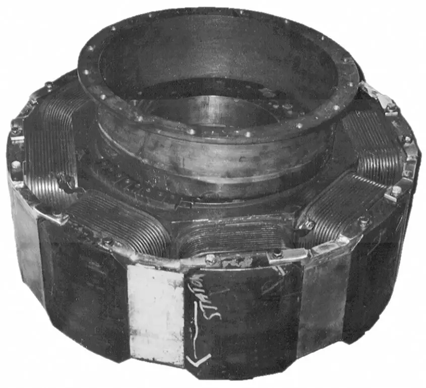
Figure 2. Salient-pole rotor diagram
Figure 3 shows a round rotor for a synchronous generator. The pole-faces are at the top and bottom of the rotor as it is positioned in the picture. Note that putting more than two poles on the rotor in slots becomes very complicated.
Figure 4 shows slip rings and brushes that are located on the end of the shaft of a 10 MW synchronous generator. This particular generator is a two-pole machine, which means it runs at 3600 RPM. Of course, the carbon in the brushes eventually wears down and the brushes have to be replaced. To keep from shutting the machine down, that has to be done while the machine is running.
Figure 5 shows a cutaway view of a synchronous generator that is designed to be driven by a diesel engine. This machine has a salient-pole rotor, and an exciter machine is located at the left end of the shaft. This exciter is a permanent- magnet machine with the armature on the rotor. The AC is rectified by diodes on the rotor to provide DC for the main field winding. This is referred to as a rotating-rectifier exciter.

Figure 3 Round rotor for a synchronous generator with wound field coils
Stator
The other half of the machine in Figure 1 is the stator, which contains the AC armature winding. Depending on the size of the machine, the armature winding consists of coils or copper bars laid into slots on the inside surface of the stator.
Figure 6 shows the armature winding that surrounds the rotor of Figure 2. This winding consists of coils in slots, and the complete structure is approximately 4 feet in diameter.
Figure 7 shows a lamination for the stator of a small AC machine (the lamination is about four inches wide). For machines like the one shown in Figure 6, the coils would be wound and then placed in the slots of the stator; for small machines like the one in Figure 7, the coils would be wound directly into the stator lamination stack.
Because AC currents will flow through the stator winding, the stator must be constructed of laminations to reduce the eddy current losses. The slots shown in Figure 7 are designed to have coils wound into them since there are teeth at the openings of the slots.
Finally, Figure 8 shows a close-up view of several slots of the armature winding of a 345 MVA machine. The inside diameter of this machine is about 9 feet. This winding is composed of copper bars laid into the slots, so essentially each coil contains one turn.
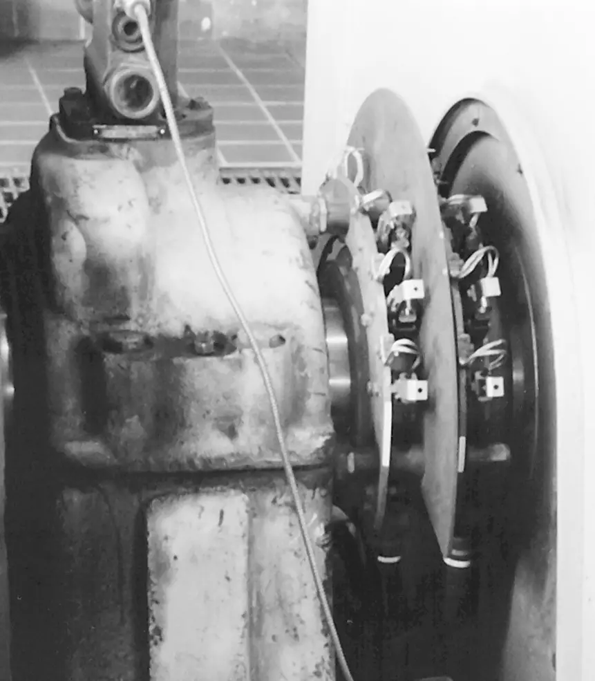
Figure 4 Slip rings and brushes diagram in a synchronous generator
Before we consider the motor and generator operation of the synchronous machine, we need to first consider how a three-phase armature winding creates a rotating magnetic field.

Figure 5 Cutaway view of a synchronous machine labeled diagram
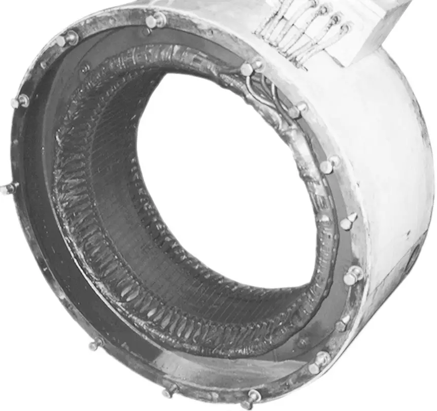
Figure 6 Stator (armature) winding of a synchronous machine diagram
Synchronous Machine Working Principle
The rotating magnetic field
Figure 9 shows two stator windings from AC machines. The stator on the left contains a complete winding, so the end turns are visible. The end turns were cut off the winding on the stator on the right side, exposing the coil turns in the slots of the stator. These stators contain a three-phase, six-pole winding so there are quite a few coils visible on the winding at the left.
To consider the operation of a three-phase winding, we will start by looking at a single phase.

Figure 7 Stator lamination of a small AC Synchronous machine
Figure 10 (a) is a sketch of the cross-section of a stator with a single-phase coil. In order to produce the desired flux distribution in the air gap, the coil occupies several slots around the stator surface. This is referred to as a distributed winding. The other two phases would be centered 120° apart, and all of the stator circumference would contain slots.
Consider what happens if an AC current, ${{I}_{m}}\cos \left( \omega t \right)$, is applied to the coil in the direction shown (X indicates current into the page and • indicates current out of the page). At time zero, the current will cause magnetic flux through the rotor in the down direction, as shown. Note that no matter what the magnitude of the current in coil a, the flux due to the current will always lie along the coil an axis. At Ɵ = 0° (the top), the flux is entering the air gap from the stator—define that to be positive.
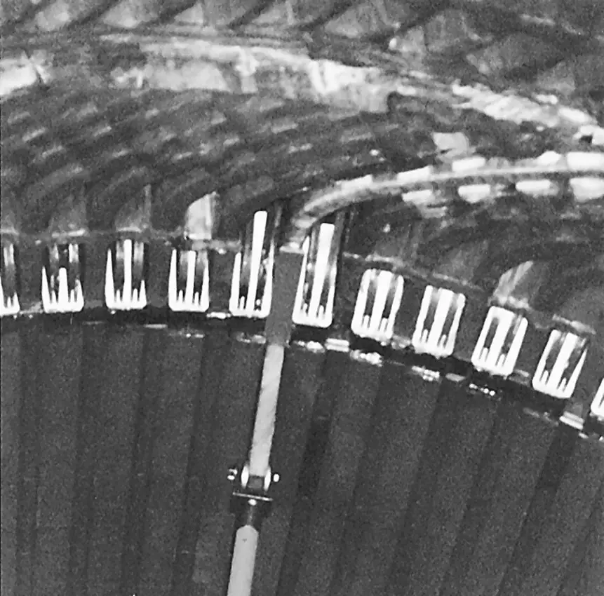
Figure 8 Armature winding and slots of 345 MVA synchronous machine
At the opposite side (Ɵ = 180°), the flux enters the air gap from the rotor, so it is negative. By proper design of the winding, the flux can be made to be sinusoidally distributed in the air gap.
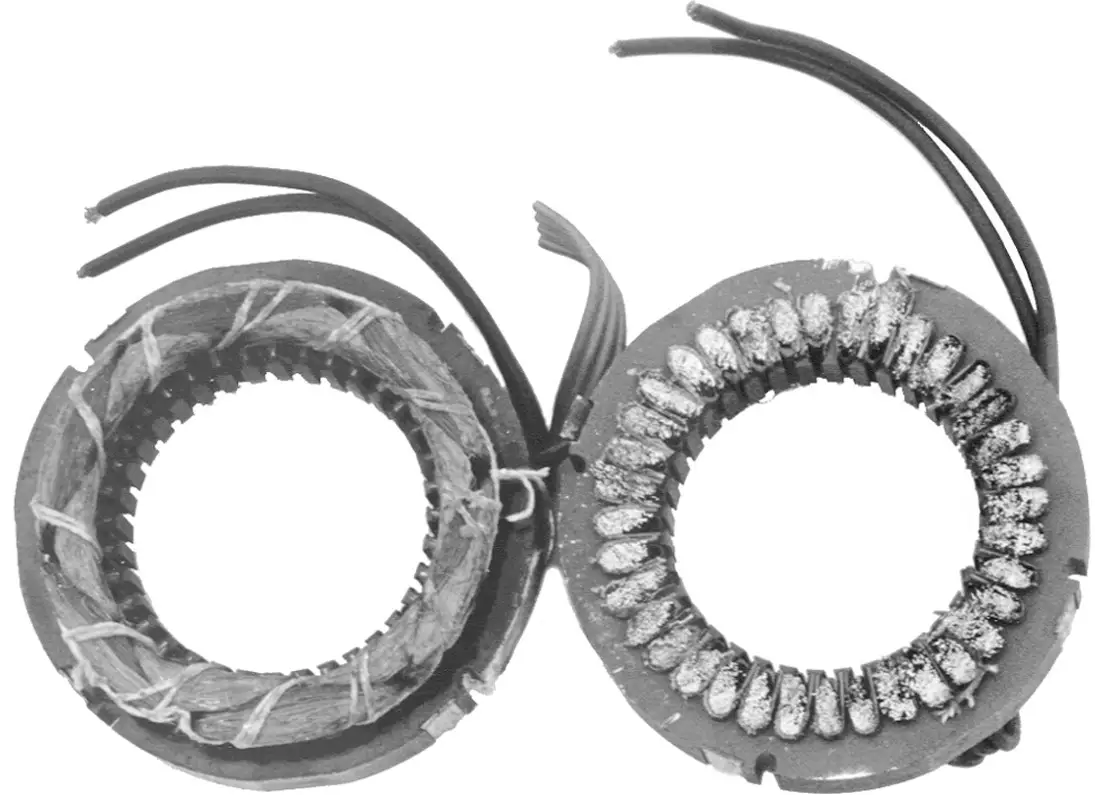
Figure 9 Left: AC stator winding. Right: end turns cut off to expose coils in slots.

Figure 10 Flux distribution in the air gap due to a single-phase coil in a synchronous machine
Imagine that we could “unpeel” the air gap of the machine and view the flux distribution in the air- gap.
At $\omega t=0$, the air gap and flux distribution might look like Figure 10(b). The dotted line indicates the center of the air gap, with the stator on top and the rotor on the bottom. At this instant in time, the current is constant, so B is a function only of Ɵ; i.e.,
$B\left( \theta \right)={{B}_{m}}\cos \theta $
where Bm is a function of the current, ${{I}_{m}}$.
Likewise, when the current reverses, at $\omega t=\pi $, the B field will look like that shown in Figure 10(c), with the positive maximum at Ɵ = 180°. At other times, the flux wave will be somewhere between the extremes, as shown in 10(d). In other words, the flux density in the airgap is a standing wave. Thus,
$B\left( \theta ,t \right)=B\left( \theta \right)\cos \omega t={{B}_{m}}\cos \omega t\cos \theta $
But by using trigonometric identities,
$\cos \theta \cos \omega t=0.5\left[ \cos \left( \theta -\omega t \right)+\cos \left( \theta +\omega t \right) \right]$
The first term on the right side, $\cos \left( \theta -\omega t \right)$ is the expression for a traveling wave in the forward direction. Since our airgap is actually circular, the wave is traveling around or rotating. Unfortunately, the second term on the right side represents a wave traveling backward around the air gap. Despite the presence of opposite traveling flux waves, single-phase motors will run once started. However, they have no starting torque because of the opposite traveling waves.
A three-phase stator winding
Figure 11 shows a three-phase stator winding. The phase windings would each occupy a number of slots as shown previously; however, each phase winding is represented by only one slot to keep the drawing legible. When the winding is shown in one slot, it is called a concentrated winding. Note that the windings of the three phases are physically 120° apart.
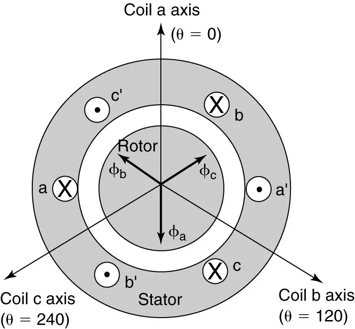
Figure 11 Three-phase stator with the same current in all three phases in a synchronous machine
In Figure 11, all three phases have the same current (represented by • and X). As a result, the flux distribution due to coil b is 120° behind coil a, and the flux due to coil c is 120° behind coil b, as shown. Since they have the same magnitude and are 120° apart, they will add to zero.
Thus, if we apply a DC current or the same AC current to all three coils, the fluxes of the three phases would cancel. That obviously wouldn’t help much.
Instead, consider what happens when a balanced three-phase set of currents is applied to the coils:
$\begin{align} & {{i}_{a}}\left( t \right)={{I}_{m}}\cos \omega t \\ & {{i}_{b}}\left( t \right)={{I}_{m}}\cos \left( \omega t-{{120}^{o}} \right) \\ & {{i}_{c}}\left( t \right)={{I}_{m}}\cos \left( \omega t-{{240}^{o}} \right) \\\end{align}$
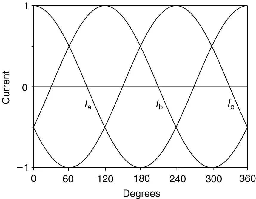
Figure 12 Balanced three-phase currents applied to the stator winding
The balanced set of three-phase currents that are applied to the stator winding are shown in Figure 12. Each current will create a magnetic flux distribution, but the three phases are displaced both in time and in space.
We could multiply the currents by the spacial distribution of the flux as was done previously and then add the three together. The result would be a traveling wave of constant magnitude.
Rather than go through the algebra and trigonometric identities, we will instead consider a physical description of the machine.

Figure 13 Rotating magnetic field created by a three-phase winding in a synchronous machine
Figure 13 shows how the magnetic field of the stator varies with time as the currents in the three-phase coils change.
At time zero, the current in phase a is at a positive maximum, while the other two phases have negative currents with an amplitude of 1/2 the current in phase a, as shown in Figure 12.
For purposes of this discussion, let positive currents enter (designated by X) the coil side labeled by just a letter (e.g., a) and come out (designated by •) the side labeled by the letter and a prime symbol (a’).
The large dot and thick X indicate a current with peak magnitude; the smaller dot and thin X indicates a smaller magnitude. Based on this, at t = 0° in Figure 13, a large positive current enters side a, while smaller negative currents enter sides b’ and c’. Conversely, the currents come out of sides a’, b, and c.
Notice the pattern that is formed—all of the currents enter the coils on the left side of the machine and come out on the right side. By the right-hand flux rule, the stator flux is directed in the downward direction, as shown by the arrow. As a result, the south (S) pole is at the bottom and the north (N) pole is at the top (θ = 0).
Now consider what happens at ωt= 60°. Ic has reached its negative peak, while Ia and Ib are both at one-half of the positive peak. So now phase c has the large dot and thick X, while the other two phases have a small dot and thin X. Because 7b went from negative to positive, its dot and X have changed sides (X at b and • at b’) Note that the pattern of dots and Xs has rotated. Again applying the right-hand flux rule, we find the direction of the stator flux has moved by 60°.
Continuing every 60°, we find that each 60° increment in time causes a 60° rotation in the magnetic flux. We are not constrained to looking at 60° intervals; however, we could look at any instant in time and find that the direction of the flux has rotated by the same angle that the currents have moved through. The stator poles are rotating, one revolution per cycle of current since this is a two- pole machine.
Mathematically, it can be shown that the peak of the flux wave is constant and rotating at a) radians per second. The direction of rotation was determined by the connections to the stator windings. By switching connections to any two phases, the direction of rotation could be reversed.
The rotational speed of the stator field is called synchronous speed. For a two-pole machine, the speed of the stator field in RPM is 60 times the frequency, but for more than two poles, we must divide by the number of pole pairs (P/2). Repeating equation 1, synchronous speed is defined as
$\begin{matrix} {{n}_{s}}=\frac{120\times f}{P}in\text{ }RPM & {} & \left( 1 \right) \\\end{matrix}$
Where f is the electrical frequency, and P is the number of poles in the machine. There are 60 seconds per minute, so dividing equation 1 by 60 yields the synchronous speed in revolutions per second:
$\begin{matrix} {{n}_{s}}=\frac{2\times f}{P}in & rev/s & \left( 2 \right) \\\end{matrix}$
The electrical frequency determines the speed of the rotating magnetic field, which in turn determines how fast the motor will run.
Synchronous Machine Key Takeaways
Understanding the construction and operation of synchronous machines is essential due to their critical role in modern electrical and industrial applications. The use of electromagnets in rotors—whether in salient-pole or round-rotor configurations—offers design flexibility for machines of various sizes and speeds. The stator’s distributed three-phase windings create a rotating magnetic field, a key principle that ensures efficient torque production and synchronous operation with the power supply. These machines are widely used in power generation (e.g., synchronous generators in power plants), industrial motor drives, and grid stability systems due to their constant-speed characteristics and high efficiency.