The article discusses the concept of commutation in DC generator, explaining how it ensures unidirectional current flow and the factors that affect its effectiveness. It also covers the causes of sparking during commutation, methods to improve commutation, and how to address issues related to self-inductance and armature reaction.
The voltage induced in a single coil of a DC generator is alternating. A commutator is therefore necessary to ensure that the current in the external circuit always flows in the one direction. During the brief interval when a coil is short-circuited by a brush, the current in the coil must reverse its direction. This reversal of armature current in a coil as it passes beneath the brush is called commutation.
In a wider sense, commutation has come to be a jargon term referring to the sparking that occurs during commutation. In either of these cases good commutation occurs when there is little or no sparking between the commutator and the brushes, which can only occur when commutation takes place at the lowest energy state of the coils, in the neutral plane.
The major factors opposing ideal commutation are:
| 1. | Self-inductance of the coil undergoing the current reversal process |
| 2. | Armature reaction. |
Speed of rotation has some influence because increasing speed reduces the time available for the commutator switching action. Irregularities in the commutator surface can cause the brushes to hop, or skip across the surface, sparking each time the brush jumps. Sparking brushes wear faster and can burn the edges of the commutator bars.
Coil Current Reversal
Figure 1(a) shows a coil X about to undergo commutation. The DC generator is shown as supplying a current of 2Ia amperes to the load, half of which is passing through this coil and the other half passing through the other side of the armature.
A short period of time later the brush has made contact with segments 2 and 3 (Figure 1(b)) and coil X has been short-circuited. The load current stops flowing through coil X and flows direct to the load through the adjacent coils and segments 2 and 3.
When the coil is short-circuited and the current stops flowing, the magnetic field about the coil collapses, producing a self-induced voltage in the coil. Because of the short-circuit this self-induced voltage sets up a comparatively high circulating current through the coil and the short-circuit.
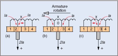
Figure 1 Reversal of current flow during commutation
After another short interval the brush breaks its contact with segment 2 and also open-circuits the high circulating current in coil X, causing sparking between the brush and the commutator. At the same instant the current to the load starts to flow through coil X again, but in the opposite direction (see Figure 1(c)).
There are two direct methods to correct for this type of commutation problem.
One is to use brushes that have a higher contact resistance, the other is to shift the brushes slightly out of their correct position in the magnetic neutral plane. This produces a generated voltage in the coil, opposing the self-induced voltage and partially cancelling it.
The first method leads to the production of heat at the commutator surface and increased losses, while the second has the disadvantage of needing to be adjusted each time there is a load change.
Because armature reaction leads to somewhat similar commutation problems, there are self-adjusting methods that are suitable for counteracting both self-induction and armature reaction.
As a general principle, commutation problems due to armature inductance are countered by altering the position of the brushes, while those due to armature reaction are countered by the addition of special windings.
Commutation in DC Generator Key Takeaways
Understanding and optimizing commutation is essential for the efficient and reliable operation of DC generator, especially in practical applications where consistent and smooth current flow is critical. Effective control of factors like self-inductance and armature reaction not only minimizes sparking and wear but also enhances the overall performance and longevity of the generator in industrial, automotive, and power generation systems.