The article provides an overview of stepper motor, including their types—permanent-magnet, variable-reluctance, and hybrid—and explains their construction and working principles. It also discusses their operational modes, such as stepping and slewing, and how these affect torque and precision.
Stepper motors are close relatives of brushless DC motors. The brushless DC motor is used where continuous motion is required, such as a fan or a disk drive. The stepper motor, on the other hand, is designed to move infinite increments (steps) in either direction and to keep track of how many steps have been taken at any point in time. The stepper motor can be used with mechanical linkages to provide precise positioning. There are three types of stepper motors, which we will describe here.
Permanent-Magnet Stepper Motor
A permanent-magnet stepper motor is similar in construction to the brushless DC motor. Figure 1 shows a cross-section of a permanent-magnet-rotor stepper motor.
The rotor contains a north and a south pole. The stator contains four salient poles—a and a’ and b and b ‘—which may contain one or two windings. If one winding is used, then the switching circuitry must be capable of delivering AC current to the winding. If two windings are used, they are wound in opposite directions. This is sometimes called a bifilar winding.
With a bifilar winding the current source delivers current in the same direction, but by selecting which winding to excite, the stator pole can be either north or south.
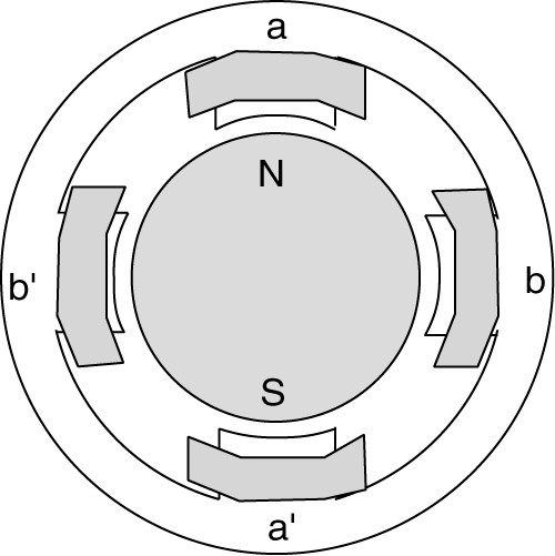
Figure 1: Permanent-magnet stepper motor.
If the voltage is applied to coil a-a’ in Figure 1 in such a way as to create a south pole at a and North Pole at a’, then the rotor would be pulled into the position shown.
If coils a and a’ are deenergized and power is applied to coils b and b’, then the rotor will rotate 90° to line up with the b and b’ coils. The direction it rotates would be determined by whether b or b‘ is the North Pole. The process could be continued by switching back to coils a and a’ in the opposite direction that they had originally. In this case, each time the rotor moves, it moves 90°.
Many other designs are possible that allow much smaller steps, even less than a degree. If the power is removed from a permanent- magnet stepper motor, the motor will remain in its position because the magnetic flux of the rotor prefers the low reluctance path created by the salient poles a and a ‘. This is called a detent torque.
Variable-Reluctance Stepper Motor
As we know that the magnetic flux prefers a low reluctance path, the variable-reluctance stepper motor makes use of this phenomenon. As shown in Figure 2, the rotor has salient poles, which create low reluctance paths when the salient pole is aligned with the stator poles and a high reluctance path when they are not aligned.
The motor in Figure 2 provides a 90° step and operates much like the permanent-magnet stepper motor in Figure 1. The primary difference is that the variable reluctance motor is free to rotate when there is no power applied; i.e., it has no detent torque.
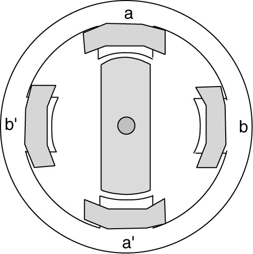
Figure 2: Variable-reluctance stepper motor with two rotor poles and four stator poles.
Many other designs are possible. Figure 3 shows a motor with four poles on the rotor and six on the stator. It is necessary that the rotor and stator have different numbers of poles to provide stepper action.
In Figure 3, rotor poles 1 and 2 are aligned with coils a and a’. The other two rotor poles are not aligned with stator poles as they are located between the b and c coils. Specifically, they are 30° from being aligned with either b or c. Thus, by applying power to the b and b’ coils, the rotor would move 30°. At that point, rotor poles 3 and 4 would be aligned with stator poles b and b’, and rotor poles 1 and 2 would be between the a and c coils.
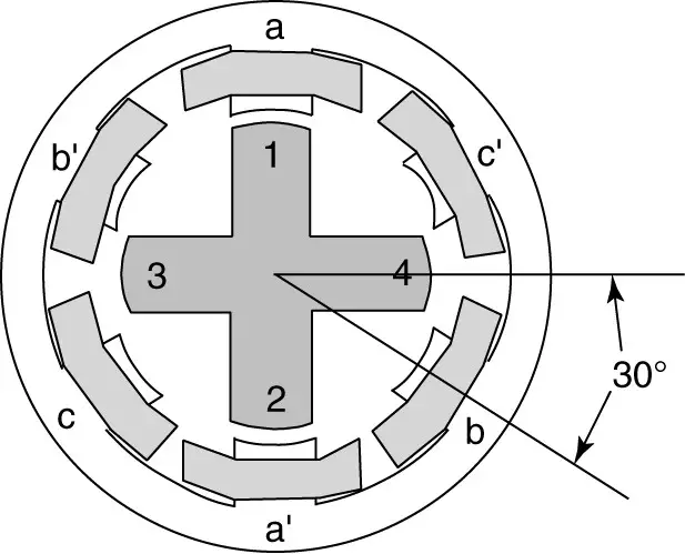
Figure 3: Variable-reluctance stepper motor with four rotor poles and six stator poles.
Obviously, if we want to have smaller steps, we need to have more rotor and stator poles.
Variable-Reluctance Stepper Motor Operation
The operation of an actual variable-reluctance stepper motor is shown in Figure 4. The stator has slots machined into the surface of the pole-faces, creating a large number of “mini-poles.” Each of the six pole faces has five teeth. There is also room for an additional tooth between poles, so there are essentially 36 teeth around the periphery of the stator. Thus, each tooth represents 10° of motion. The rotor also has teeth machined into its surface, in this case, 32 teeth.
In Figure 4(a), the teeth are aligned at the top and bottom of the motor, as indicated by the arrows. This corresponds to exciting the coils at the top and bottom. Note that one of the teeth at the bottom is marked with a line.
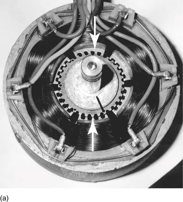
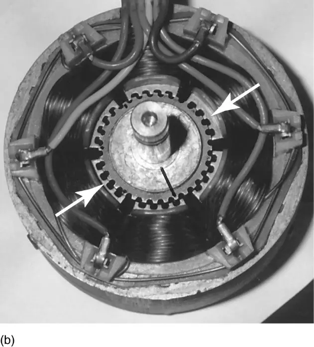
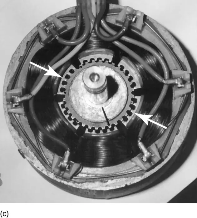
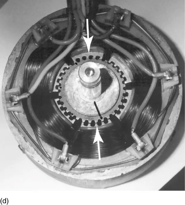
Figure 4: Operation of a variable-reluctance stepper motor. Arrows indicate alignment of rotor and stator poles.
If power is removed from the top and bottom coils and applied to the two coils marked by arrows in Figure 4(b), the rotor rotates to align the teeth at those poles, as shown.
Looking at the bottom figure, we observe that the tooth marked with a line has only moved part way to the next tooth. The process continues in Figure 4(c) and the marked tooth at the bottom still hasn’t reached the next tooth on the stator.
Finally, power returns to the top and bottom coils in Figure 4(d), and the marked tooth completes its movement to the next stator tooth. Thus, it took three steps to move 10°, or 3.33° per step.
Hybrid Stepper Motor
The hybrid stepper motor combines the features of the permanent magnet and the variable-reluctance stepper motors.
Figure 5 illustrates the principles of the hybrid stepper motor, and Figure 6 is a photograph of a hybrid stepper motor.
The rotor of the hybrid stepper motor has salient poles; however, for cost purposes, a permanent magnet is mounted between two ferromagnetic armatures, as shown in Figure 5(b). Thus, one armature always contains north poles and the other armature always contains south poles.
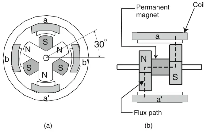
Figure 5: Sketch of a hybrid stepper motor. a. Top view. b. Side view of rotor and stator poles.
As shown in Figure 5(a), the top of the rotor has three north poles 120° apart, and the bottom has three south poles, also 120° apart. However, the north and south poles are displaced by 60°. In the position shown, the south pole at the top of Figure 5(a) faces stator pole a, and the north pole at the lower part of the figure faces stator pole a’. This creates a flux path, as shown in Figure 5(b), through the North Pole, the permanent magnet, and the South Pole. The flux would complete its path through the stator, which is not shown in Figure 5(b).
If power is removed from the a and a’ coils, there is still a detent force due to the flux of the permanent magnet on the rotor.
When power is applied to coils b and b’, there will be a force that causes the rotor to move poles into alignment with stator poles b and b’. The direction of rotation will depend on the polarity of the voltage applied to the coils, but in either event, a step of 30° will result.
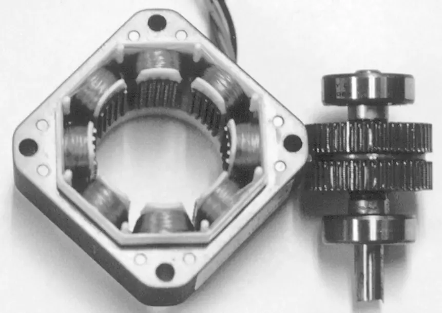
Figure 6: Photograph of hybrid stepper motor stator and rotor.
Thus, this geometry machine would have a 30° step. As with the reluctance stepper motor, the size of the steps can be reduced by putting more poles on the rotor and cutting teeth into the stator poles.
Figure 6 is a photograph of the stator and rotor of a hybrid stepper motor. The two sets of rotor poles are sandwiched around a piece of permanent magnet material, and the teeth of the two sides of the rotor do not line up, as was described earlier.
Operation of the Stepper Motor
When operating in the stepper mode, the motor essentially starts and ends each step at rest. The pause between steps can be on the order of milliseconds, however, so rapid stepping is possible. The rate at which the motor can be stepped is a function of the inertia of the motor and load and the load torque. There is also some settling time for the rotor to reach its final position after being commanded to step.
The amount of torque that the motor can deliver is a nonlinear function of the current that is applied to the stator poles.
Under some circumstances, it may be desirable to operate the stepper motor continuously, i.e., without pausing between steps. Such operation is called slewing.
When the motor is in the slewing mode, it does not have to accelerate and decelerate the inertia of the motor and load, so it can deliver a higher torque than when stepping. However, if too much load torque is applied to the motor, it can lose a step and the positioning of the load may be inaccurate.
Stepper Motor Types Key Takeaways
Understanding the different types of stepper motors—permanent-magnet, variable-reluctance, and hybrid—is crucial for selecting the right motor for precise motion control applications. Each type offers unique characteristics in terms of torque, step size, detent behavior, and structural complexity. These distinctions become particularly important in practical use-cases such as robotics, CNC machinery, 3D printing, and automated manufacturing systems, where accuracy, repeatability, and controlled motion are essential. The ability of stepper motors to provide incremental movement without feedback systems makes them cost-effective and reliable for tasks that demand exact positioning. Their modes of operation, including stepping and slewing, also provide flexibility in balancing torque output and speed.