The article covers the basics of digital electronic circuits, explaining the binary number system, decimal-to-binary conversion, binary addition, voltage logic levels, and how bits, nibbles, and bytes relate to digital information processing.
What is Binary Number System?
Digital electronic circuits can be made to act in only two states: on and off. This two-state system is called a binary number system. This system can be compared to a single-pole, single-throw (SPST) switch, Figure 1.
A switch in the off position represents a 0 in the binary numbering system. Likewise, a switch in the on position represents a 1. It is not practical to build large electronic logic circuits using manual switches. Manual switches do, however, provide a good basis for understanding other switchable electronic components, Figure 2.
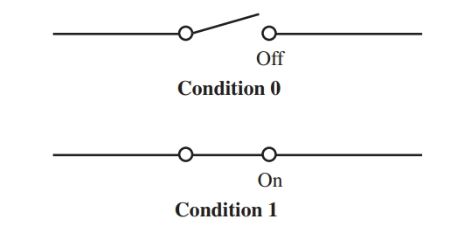
Figure 1. A single-pole, single-throw switch as a binary number system.
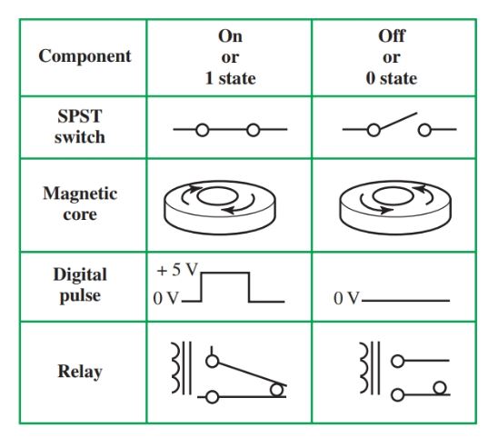
Figure 2. Binary states of components.
The transistor is the most common electronic component that can be used as a switch. The transistor can allow current to flow. This is an on, or 1, state. Or it can stop current from flowing. This is the off, or 0, state. See Figure 3.
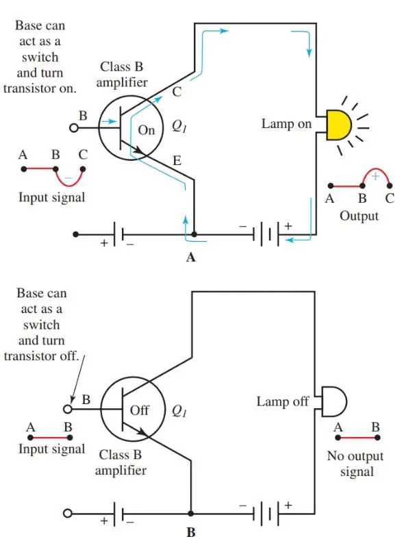
Figure 3. Diagram of transistor acting as a switch. A–On. B–Off.
Class B amplifiers are biased at the midpoint of the curve produced by the emitter voltage and collector current.
Without any input signal (point A to B in Figure 3) the amplifiers are turned off. If the input signal changes to a negative level (B to C), the emitter-to-base bias will be decreased. This condition causes the output signal across the lamp to swing positive (input signal is 180 degrees out of phase with the output signal in a CE circuit).
- You May Also Read: Number Systems in Digital Electronics
With only one SPST switch, we can produce only two outputs: 0 and 1. With additional switches, we can count higher. To understand how to count to a higher number such as 45 or 79 with switches that are either on or off, we must learn the binary system.
There is a basic rule for counting in any system. Digits must be recorded one after the other for each counting unit. This continues until the count exceeds the total number of digits available. Then, a second column is started and counting continues.
How Binary Number System Works
In the number system you are accustomed to, the decimal system, there are 10 digits available. Each time the count is raised from 0, you place the next highest digit (0, 1, 2, 3, … 9). This takes you from 0 through 9. Nine is the last digit available in the decimal system. Thus, it is time to start the second column and continue (10, 11, 12, …).
The binary number system works as shown in Figure 4. Since only two digits are available in the binary number system, when you reach 2, you must start a new column. The digit 0 in the decimal system is 0 in the binary system.
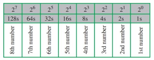
Figure 4. The binary number system working
Likewise, the digit 1 in the decimal system is 1 in the binary system. However, the number 2 in the decimal system is number 10 in the binary system. There is no digit 2 in binary, so you have to move into the second column to create the number 2.
Decimal to Binary Conversion
The binary number for 6 is 110, Figure 5. Figure 6 shows the decimal to binary conversion for the numbers 0 through 26. Try to extend this table to 50.
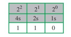
Figure 5. Binary number for decimal number 6.
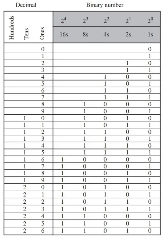
Figure 6. Decimal to the binary conversion table chart.
If you are having trouble with binary numbers, try this activity. It may help you understand the binary numbering concept.
Tear off five small pieces of tape. Number the tape as shown in Figure 7. Place one piece of tape on each finger of your left hand with palm up (in the order shown).
Fingers pointing up represent ls. Fingers folded down represent 0s. Position your hand as shown in Figure 8. What is the binary number? What is its decimal equivalent?
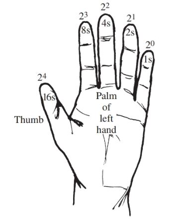
Figure 7. Learning the binary number system.
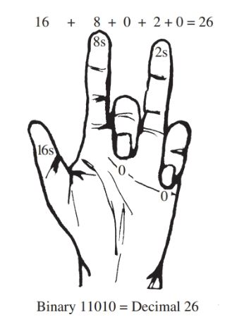
Figure 8. Converting 26 decimal to 11010 binary.
A larger decimal number, 79, is shown in binary form in Figure 9.
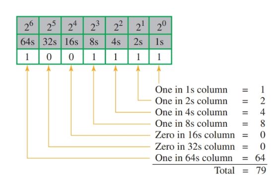
Figure 9. Binary number for decimal number 79.
Binary Numbers Addition
Binary addition is a simple process, Figure 10. When adding 0 and 0, the sum is still 0. When adding 1 and 0, the sum is 1. But adding 1 and 1 produces the sum 10. The 0 is placed in the ls column. The 1 is carried to the 2s column.
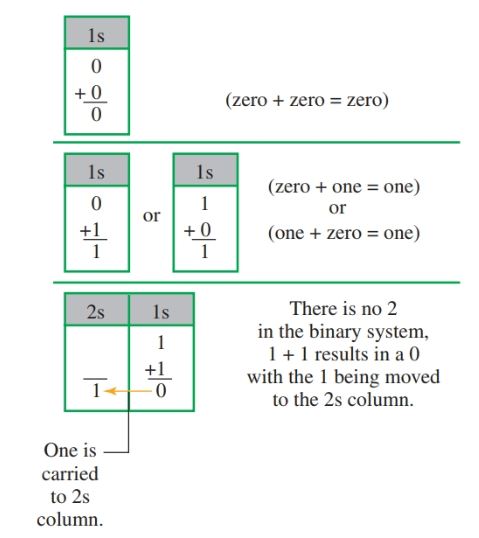
Figure 10. Binary number addition fundamentals.
To add two larger binary numbers, the same steps are followed. Figure 11 shows the addition of 57 (00111001) and 24 (00011000). Figure 12 is a chart for a comparison of some common electronic numbering systems.
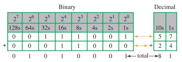
Figure 11. Binary addition of 57 and 24.
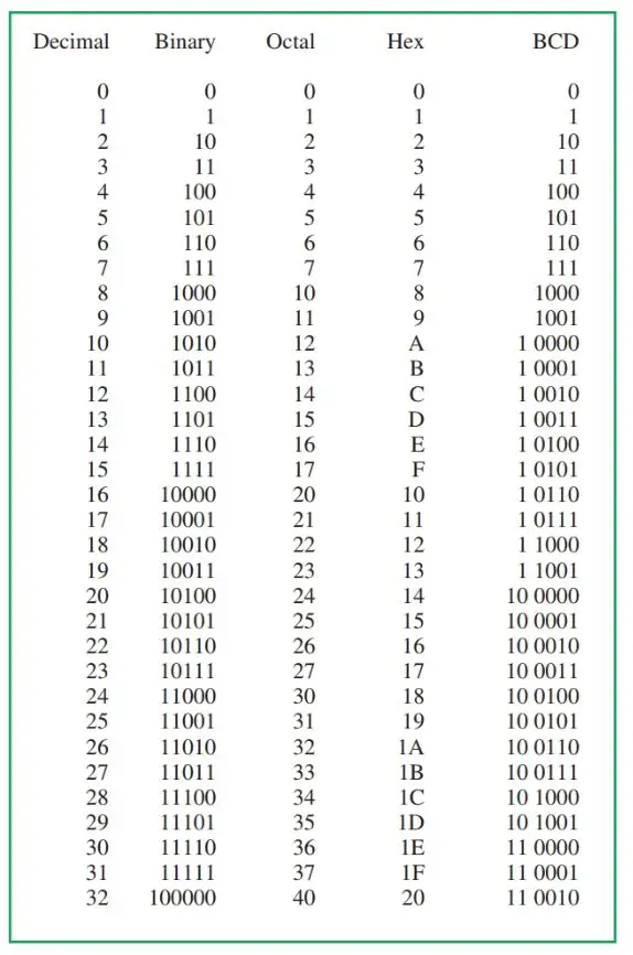
Figure 12. Comparison of common electronic numbering systems.
Voltage Logic Levels in Digital Circuits
We know that digital circuits have only two states of 0 and 1. The operating voltages needed in a circuit for these two values depending on the type of logic circuitry or family used. Regardless of the logic family used, in positive logic, the high value of 1 is called the valid logic high range. This value most often varies from 2 to 3.5 volts to 5 volts.
The low value, or 0, varies from 0 volts to 0.8 to 1.5 volts. This value is shown as the 0 to V1 range in Figure 13. This is called the valid logic low.

Figure 13. Logic levels for digital circuits.
The area between these two values acts as a buffer range. Any voltage in this range applied to the digital circuit causes confusion in the IC. The IC will not know whether to produce a 0 or a 1. This area is called the invalid value range, or the intermediate range. In Figure 13, this range is shown between V1 and V2.
What are Bits, Nibbles, and Bytes?
In binary code, the smallest unit of information is called a bit. The word “bit” comes from joining the two words, binary digit. A bit can be either 0 or 1. It is only one column or digits in a binary numbering system, Figure 14.
Four bits of information make up a nibble.
Two nibbles, or eight bits, make up a byte.
A byte is a single unit of memory in a computer. For example, a computer with a 256-byte storage can hold 2048 bits of information. This is a small number, however.
Most computer memory is given using the terms kilobytes, megabytes, or gigabytes. Computer storage abilities continue to grow.
| Term | Symbol | Numeric Value |
| Kilobyte | K | 1000 |
| Megabyte | M | 1,000,000 |
| Gigabyte | G | 1,000,000,000 |
| Terabyte | T | 1,000,000,000,000 |
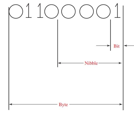
Figure 14. Bits versus nibbles versus bytes.
Binary Number System Key Takeaways
Understanding the basics of digital electronic circuits—such as the binary number system, decimal-to-binary conversion, binary addition, voltage logic levels, and units like bits, nibbles, and bytes—is essential for grasping how modern electronic devices operate. These concepts form the foundation of all digital systems, including computers, smartphones, and microcontrollers. Applications ranging from data storage and processing to signal transmission and circuit design rely heavily on binary logic and digital information representation.