The goal of this module is to provide learners with skills and practice necessary to enable them to convert between number systems used in digital electronics.
Objective
The learner will be able to
- Explain the difference between analog and digital quantities
- Give examples of binary numbers describe their structure
- Give examples of hexadecimal and octal number systems and be able to convert between binary, hexadecimal, and octal number systems
- Use a calculator to perform number system conversion and hexadecimal arithmetic
- Describe logic levels used in digital systems and analyze the characteristics of a pulse waveform
- Discuss the elements that make up a digital system
Orienting Questions
- What is the difference between analog and digital quantities?
- What is the binary number and how do I use it?
- What is the Hexadecimal number system?
- How do I convert between number systems used in digital electronics?
- What are logic levels in a digital system?
Introduction
Knowledge of number systems is essential to the study of digital electronics. This module will focus primarily on binary number systems. However, for completeness, octal and hexadecimal number systems and their relationship to binary numbers will also be covered. Also, we will discuss logic levels in digital systems and discuss the instruments used to analyze digital circuitry.
Analog vs. Digital Signals
Before we can discuss any topics in digital electronics, an understanding of the difference between analog and digital signals must be addressed. If you have taken a course already in AC, and DC electronics, you have already been exposed to analog signals. An analog signal is defined as a continuously varying signal for all time. Figure 1 provides an illustration of an analog signal.

Figure 1. Analog Signal
Note the continuous nature of the AC signal above over time. There is an infinite number of possible values of the waveform within the sample time domain. This is an image of a single frequency audio tone. The maximum amplitude corresponds to the loudest volume level.
A digital signal is defined as a non-continuous signal whose values are discreet over time. An example of a digital waveform is below in figure 2.
Figure 2: Digital Signal
Note in figure 2 the discrete values, on and off, at certain times. In real digital systems, this may represent “0” for the “off” state, and “1” for the “on” state, where 0 and 1 are logic voltage levels (more on this later).
Binary Number systems
In our study of Digital Electronics, we will primarily use the binary number system. The binary number system is a base-2 or radix-2 number system, that is, it only uses two digits. The decimal number system, which we all use to count with, uses numbers 0-9 and therefore is referred to as base-10 or radix-10. The radix, as you can see, is also the base number.
Now, regardless of the number system, each number in a decimal or binary system carries a specific weight. For example, consider the following 2 numbers:
300 30
The 3 in 300 carries more weight than the 3 in 30. Therefore each digit in any number carries a different weight. Let’s look at a few examples of decimal (base 10) numbers.
- 12810 = 1 x 10² + 2 x 101 + 8 x 100
- 610 = 3 x 10² + 6 x 101 + 8 x 100 + 6 x 10⁻¹
- 4286.2210 = 4 x 10³ + 2 x 10² + 8 x 101 + 6 x 101 + 2 x 10⁻¹ + 2 x 10⁻²
Note the pattern in each example and how the position of the digit in the number determines the weight.
In binary number notation, only 2 characters are considered—0 and 1. 0 and 1 are referred to as “bits”. But to understand how to weight binary numbers, it is first necessary to be able to count in binary. The count goes a bit like this.
1, 0, 10, 11, 100, 101, 110, 111, etc.
Note the positions of the numbers above—1 digit, 1digit, 2 digits, 2 digits, 3 digits, 3 digits, 3 digits, 3digits, 3 digits, etc. The next eight positions would require 4 digits and so on. Then the a pattern will arise 1,2,4,8,16,32,etc. These are the weights of each individual position of the bit.
A general expression for the weighting of binary number positions is
2k-1……24 23 22 21 20.2-1 2-2 2-3….2-k
The left-hand digit is the MSB—most significant bit.
The right-hand digit (last number before the decimal point) is the LSB-least significant bit.
Consider the 4-bit binary number:
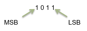
Just like for decimal base 10 numbers, the value of each individual position is added to the next position. The position which holds values of 0 does not get added to the total. So 4-bit binary weight looks something like this:
23 22 21 20.2-1
1 0 1 1 . 0
So 1011 = (1 x 23) + (0 x 22) + (1 x 21) + (1 x 20) + (0 x 2-1)
or
8 + 0 + 2 + 1 + 0 = 11
10112 = 11, 11 is the decimal equivalent of the binary number 1011
As you can see, based on weighting, that binary number 1011 has a decimal number equivalent: If we were to write all possible combinations of 4-bit binary, we could count up to decimal number 15. (see below)
| Binary Number | Decimal Equivalent |
| 0000 | 0 |
| 0001 | 1 |
| 0010 | 2 |
| 0011 | 3 |
| 0100 | 4 |
| 0101 | 5 |
| 0110 | 6 |
| 0111 | 7 |
| 1000 | 8 |
| 1001 | 9 |
| 1010 | 10 |
| 1011 | 11 |
| 1100 | 12 |
| 1101 | 13 |
| 1110 | 14 |
| 1111 | 15 |
As you can see, the 4-bit binary will count up to decimal number 15.
For n bits, you can count up to 2n – 1.
For Example, for 8-bit binary (looks like XXXX XXXX) you can count:
28 – 1 = 255, therefore 8-bit binary will count up to decimal number 255.
Binary
Binary is how we use numbers in electronics. All modern computers use binary to remember numbers. How computers remember the numbers won’t be taught in this class, but you will learn how the binary numbers come into play for computers remembering certain things.
Bits and Bytes
A bit is one symbol in a binary or one value in one column. A byte is eight bits put together.
- Binary numbers are either 0 or 1
- One bit is either 0 or 1
- Binary number systems are used in all aspects of computing
Hexadecimal Numbers
Hexadecimal is another number system used in digital electronics. The ten digits of the decimal system are used for the first ten characters of the hexadecimal system. The first six letters of the alphabet are used for the remaining six characters.
| Hexadecimal | Binary | Decimal |
| 0 | 0000 | 0 |
| 1 | 0001 | 1 |
| 2 | 0010 | 2 |
| 3 | 0011 | 3 |
| 4 | 0100 | 4 |
| 5 | 0101 | 5 |
| 6 | 0110 | 6 |
| 7 | 0111 | 7 |
| 8 | 1000 | 8 |
| 9 | 1001 | 9 |
| A | 1010 | 10 |
| B | 1011 | 11 |
| C | 1100 | 12 |
| D | 1101 | 13 |
| E | 1110 | 14 |
| F | 1111 | 15 |
Number System Conversion Example 1:
Convert the hexadecimal number 1AF16 to its binary equivalent.
Now let’s convert a hexadecimal number to its decimal equivalent. I first convert my hexadecimal number to binary and then use the sum of weights method to convert from binary to decimal.
Convert the hexadecimal number F16 to its decimal equivalent.
First, convert F16 to binary. F16 = 11112
Second, using the sum of weights method, convert 11112 to decimal.
11112 = (23 × 1 = 8) + (22 × 1 = 4) + (21 × 1 = 2) + (20 × 1 = 1)
= 8 + 4 + 2 + 1 = 1510
To convert a decimal number to a hexadecimal number, I first convert my decimal number into binary and then convert the binary number into hexadecimal.
Number System Conversion Example 1:
Convert 2010 to its hexadecimal equivalent.
First, 2010 = 101002
Next, I separate the binary number 101002 into four-bit groups starting from the LSB.
01002 = 4 and 00012 = 1
Then assign each four-bit group its hexadecimal equivalent. Therefore the hexadecimal equivalent for 2010 is
000101002 = 1416
Logic Levels and waveforms in a Digital System
In digital circuits, a logic level is one of a finite number of states that a signal can have. Logic levels are usually represented by the voltage difference between the signal and ground (or some other common reference point), although other standards exist. The range of voltage levels that represent each state depends on the logic family being used.
In binary logic, the two levels are logical high and logical low, which generally correspond to a binary 1 and 0 respectively. Signals with one of these two levels can be used in logic for digital circuit design or analysis.
Active state
The use of either the higher or the lower voltage level to represent either logic state is arbitrary and may even be changed at different levels within a system. Active-high and active-low states can be mixed at will: for example, a read-only memory integrated circuit may have a chip-select signal that is active-low, but the data and address bits are conventionally active-high. Occasionally a logic design is simplified by inverting the choice of an active level (see De Morgan’s theorem).
An active-high signal represents a binary digit of 1, or asserted state of a logical condition, by the higher of two voltages. The higher voltage represents a binary 1 or “mark”, and the lower voltage represents a binary 0 or “space”.
An active-low signal represents a binary digit of 1, or asserted state of a logical condition, by the lower of two voltages.
Logic voltage levels
The two logical states of a wire are usually represented by two different voltages, but the current is used in some logic families. A threshold is designed for each logic family. When below that threshold, the wire is “low,” when above “high”. Intermediate levels are undefined and the behavior of the connected circuits is highly implementation-specific. The problem of the circuit designer is to avoid circumstances that produce intermediate levels so that all results are predictable.
It is common to allow some tolerance in the voltage levels used; for example, 0 to 2 volts might represent logic 0, and 3 to 5 volts logic 1. A voltage of 2 to 3 volts would be invalid and would occur only in a fault condition or during a logic level transition, as circuits cannot instantly change voltage levels. However, few logic circuits can detect such a fault, and most will end up interpreting the signal as either a 0 or a 1 input, unpredictably and possibly inconsistently.
Another control on the logic probe allows selection of either TTL or CMOS family logic. This is required as these families have different thresholds for the logic-high (VIH) and logic-low (VIL) circuit voltages.
Some logic probes have a separate audible tone for each of the logical states. An oscillating signal causes the probe to alternate between high-state and low-state tones.
A logic probe is a cheap, versatile and convenient digital test instrument, but can test only a single signal at a time. When many logic levels need to be observed or recorded simultaneously, a logic analyzer is used.
Number Systems in Digital Electronics Key Takeaways
Understanding number systems such as binary, hexadecimal, and octal is essential in the field of digital electronics, as these systems form the foundation of how data is represented and processed in digital devices. Being able to convert between these systems, interpret logic levels, and analyze pulse waveforms allows engineers and technicians to design, troubleshoot, and optimize digital systems effectively. These skills are widely applicable in computer systems, embedded electronics, telecommunications, and other areas where digital signals and microprocessor-based technology are used.