The article discusses the origins of harmonics in power systems, focusing on how nonlinear electrical loads create harmonic currents due to their non-sinusoidal current draw. It also explores common sources like switched-mode power supplies, the impact of harmonics on power quality, and methods to reduce harmonic distortion using multi-pulse rectifier configurations.
Any electrical load that does not have a linear relationship between the voltage applied to it and the current through it will cause harmonic currents in the power system.
To consider what is meant by a linear load, consider Figure 1. Figure 1(a) shows a sinusoidal voltage and the current that results from applying the voltage to a resistive load. Since it is a resistive load, the current is in phase with the voltage.
Lissajou Figure Definition
Figure 1(b) shows a plot of the current as a function of the voltage. In this case, the plot is a straight line. Thus, we would say the resistor is a linear load. The cross-plot of current as a function of voltage is sometimes referred to as a Lissajou figure.
Figures 1(c) and (d) show the voltage and current and Lissajou figure for an inductor, which has some resistance as well. In this case, the current lags the voltage by almost 90 degrees. Since the current is near its maximum when the voltage is zero and vice versa, the Lissajou figure now takes on an elliptical shape. This is still a linear load, as both the voltage and current are sinusoidal.
Loads whose Lissajou figure is an ellipse, a circle, or a straight line are linear loads.
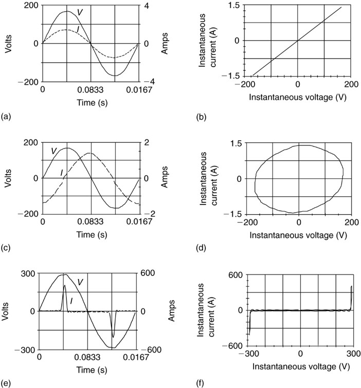
Figure 1: Voltage and current waveforms and Lissajou figures for linear and nonlinear loads.
The final two figures in Figure 1, (d) and (e), exhibit a very different relationship between the voltage and current. In this case, the current is not sinusoidal, consisting of a series of positive and negative pulses when the voltage is near its positive or negative peaks. The Lissajou figure shows very clearly that this is a nonlinear load. In particular, the current is zero except at the extreme values of voltage.
Harmonics used to be a problem only for utilities and a few large customers (e.g., metal processors using electric arc furnaces). The utilities usually impose limits on the number of harmonics the large customer could reflect into the power system, and the customer either put up with the harmonics or compensated for them.
Today the situation is very different. From the computer on everyone’s desk to adjustable-speed drives (ASDs) for induction motors and electronic ballasts in fluorescent lighting, there are nonlinear loads generating harmonics everywhere. Furthermore, they are proliferating as companies use electronics to become more efficient and utilities pay their customers to install ASDs and electronic ballasts to reduce requirements for a new generation.
It is no longer possible to ignore the harmonics for, as perverse as it might seem, the very electronic devices that create harmonic currents and distort the voltage are often very intolerant of voltage distortions. Electronic equipment creates harmonic currents because solid-state components require DC voltages to operate.
To provide DC power, many desktop computers and other single-phase electronic devices use switched-mode power supplies. Figure 2 shows an elementary power supply in which a capacitor is fed from the power system through a full-wave bridge rectifier. The diodes conduct only when they are forward biased, i.e., when the instantaneous value of the AC source is greater than the voltage across the capacitor. When this circuit is first turned on, the capacitor charges to the peak of the AC waveform (169.7 V for a 120 system), and if there is no load on the DC side, nothing else happens.
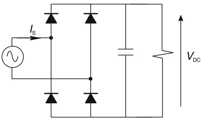
Figure 2: Simple single-phase switched-mode power supply.
More interesting, of course, is what happens when there is a load. After the capacitor is fully charged, the AC voltage waveform starts to decrease, and the diodes shut off. While the diodes are off, the capacitor discharges current to the DC load, which causes its voltage, VDC, to decrease. Thus, when the AC source becomes larger than VDC during the next half-cycle, the capacitor draws a pulse of current to restore its charge. Figure 1(e) shows the current of such a load (actually the input current to a variable-speed-motor drive). Because the current has a repetitive waveform, it is composed of a series of harmonics.
The harmonics can be found using a variety of test equipment with the capability to process a Fast Fourier Transform (FFT). This particular waveform has a large number of harmonics, as shown by the harmonic spectrum (through the 31st harmonic) in Figure 3.
Note that the first several harmonics after the fundamentals are almost as large as the fundamental. This waveform, as shown in Figure 1(e), has a peak value of 425 amps, but the rms of the waveform is only 103 amps. This leads to another quantity that is an indicator of harmonic distortion. The crest factor (CF) is defined as the ratio of the peak value of the waveform divided by the rms value of the waveform:
$\begin{matrix} CF=\frac{Peak~of~Waveform}{RMS~of~waveform} & {} & \left( 1 \right) \\\end{matrix}$
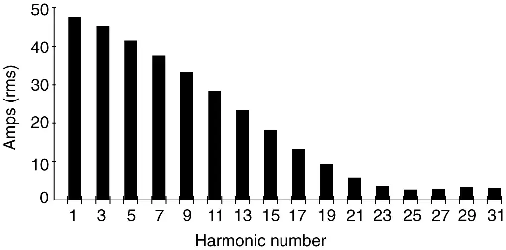
Figure 3: Harmonic spectrum of current for the circuit shown in Figure 2
For the current shown in Figure 1(e), the crest factor is 425 divided by 103, or 4.12. For a sinusoidal current or voltage, the crest factor would be the square root of 2 (1.414). A waveform whose crest factor is substantially different from 1.414 will have harmonic content. Note that the crest factor can also be lower than 1.414. A square wave, for example, would have a CF of 1.
As shown in Figure 3, the third harmonic of a single-phase bridge rectifier is very large. Putting such loads on the three phases of a three-phase system could cause problems.
One way to avoid the problems caused by the triplen harmonics is to eliminate them. Fortunately, it turns out that by using a three-phase bridge rectifier, we can eliminate the triplen harmonics.
Figure 4 shows the input current and harmonic content for a three-phase bridge rectifier (again, the input current to an adjustable-speed-motor drive). Note that the phase current now contains two pulses in each half-cycle. This particular rectifier is what is known as a “six- pulse” rectifier, since there are six diodes in the circuit. As can be seen, all of the triplen harmonics are eliminated. In fact, the only harmonics are ones having order numbers given by
\[\begin{matrix} h\text{ }=\text{ }6n\text{ }\pm \text{ }1 & {} & \left( 2 \right) \\\end{matrix}\]
Where n is any positive integer. Thus, for n = 1, we have the 5th and 7th harmonics; for n = 2, we have the 11th and 13th harmonics, etc., as shown in Figure 4.
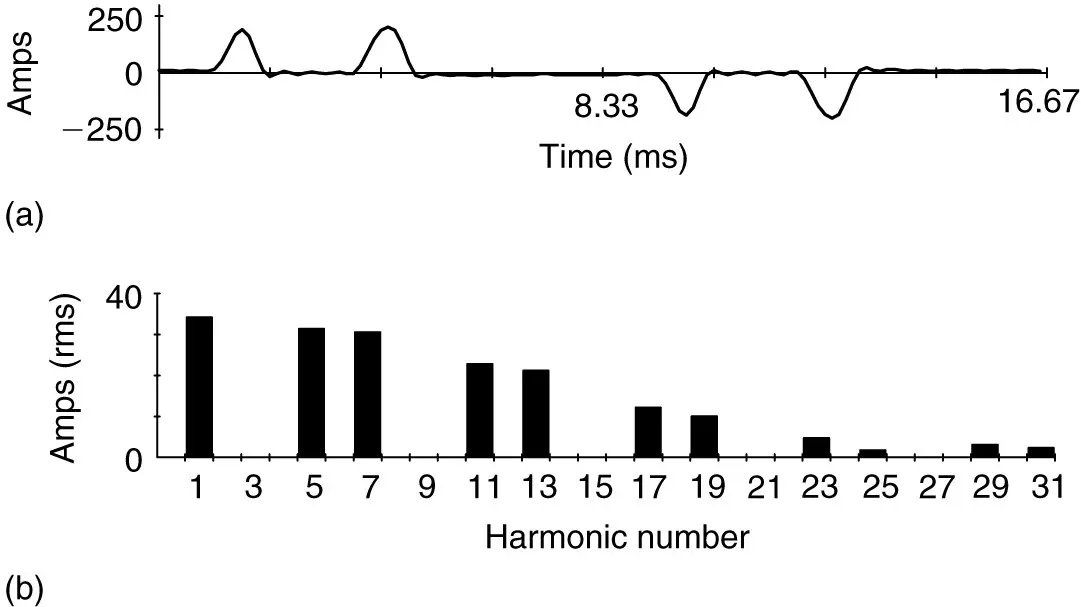
Figure 4: Line current and harmonic content for three-phase bridge rectifier.
It is also possible to build a so-called twelve-pulse rectifier by using two rectifiers, one fed from a delta winding of a transformer and one from a wye winding. The 30-degree phase shift between the delta and wye line voltages creates a six-phase system, and the 6 in equation 2 would be replaced by 12, eliminating the 5th and the 7th harmonics (among others).
Having looked at what causes harmonics currents, it is important to consider how they affect the power system.
Causes of Harmonics in Power System Key Takeaways
Understanding the origin and behavior of harmonic currents in power systems is crucial because their presence directly impacts the efficiency, reliability, and safety of electrical infrastructure. As modern electrical systems increasingly rely on nonlinear loads such as switched-mode power supplies, adjustable-speed drives, and electronic ballasts, harmonics have become a widespread concern—not just for utilities, but for every level of power consumption. These harmonic distortions can cause overheating in equipment, increased losses, interference with communication systems, and premature equipment failure. Therefore, analyzing harmonic behavior and implementing mitigation techniques like multi-pulse rectifier configurations (e.g., six-pulse and twelve-pulse rectifiers) is essential for maintaining power quality and ensuring the optimal performance of both industrial systems and sensitive electronic devices.