The article provides an overview of single-phase AC power generation, its waveform characteristics, and distribution systems. It also discusses voltage configurations, frequency standards, and basic power calculation methods in single-phase circuits.
In a single-phase (or 3-phase for that matter) AC electrical power distribution system, both the load current (as electrical utilization loads are connected) and the applied voltage that causes it to flow are transmitted along the length of the circuit conductors varying in amplitude with time and periodically reverse between positive and negative polarities.
The generation of the AC power within the alternator (AC generator or dynamo) creates a sine waveform of voltage and current that has one positive alternation and one negative alternation per cycle as demonstrated in Figure 1.
For small-scale electrical-power generation as illustrated in Figure 2, the generation of AC power is normally limited to a single-phase AC source. According to the winding and wiring configuration within the alternator, the passing of either the south or north pole of the rotating magnet, which would constitute 180 mechanical degrees, will generate either a positive or negative alternation of the electrical power from zero power to a positive or negative peak of power, and back to zero power in 180 electrical degrees.
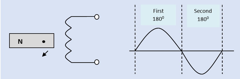
Figure 1. Generation of single-phase AC power
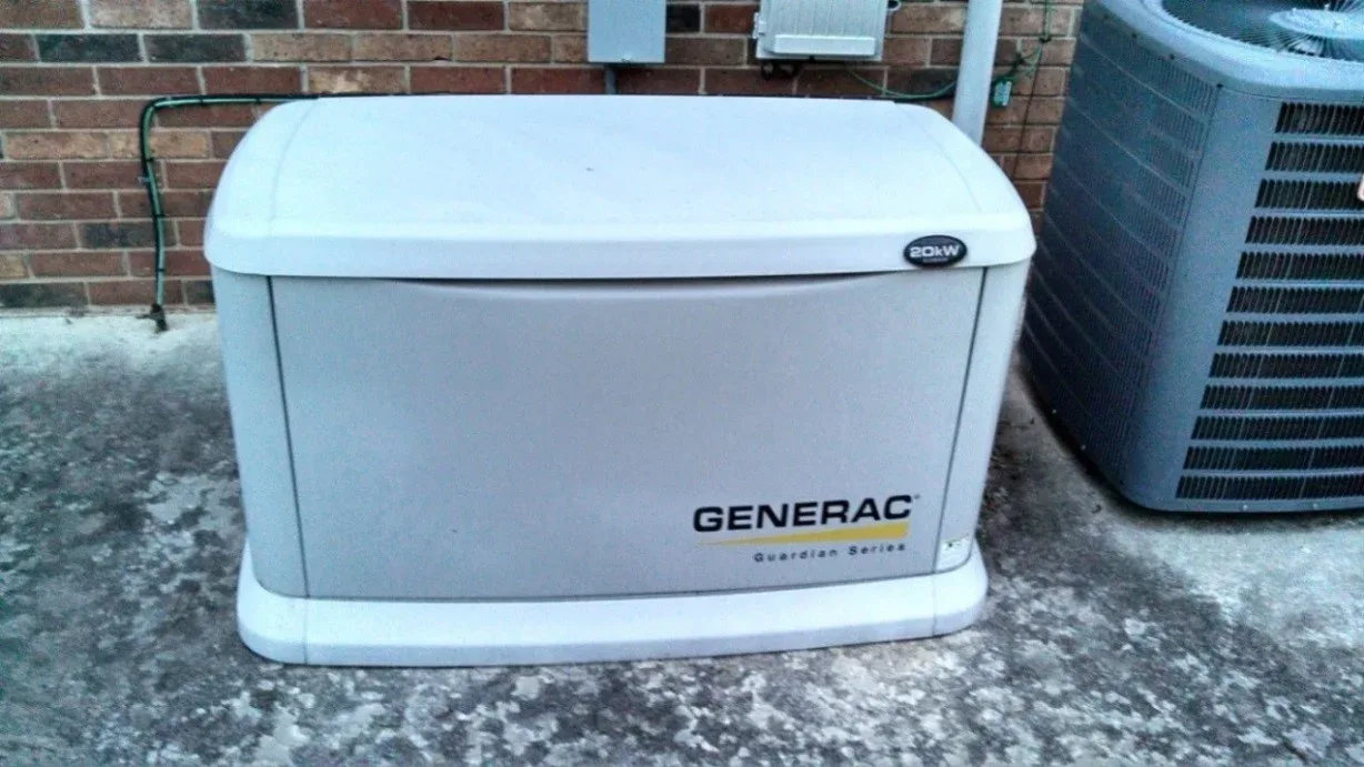
Figure 2. Small-scale single-phase AC electrical-power generation
As drawn in Figure 1, with the south pole of the magnet perpendicular to the winding, the maximum number of flux lines in the magnetic field is being reduced as the magnetic field pole passes perpendicularly across the length of the conductor in the winding: the induced voltage is at its peak in the alternation, which occurs at 90 electrical/mechanical degrees.
At the start of the alternation, or at 0 electrical/mechanical degrees, the length of the magnet was parallel to the length of the winding with the south pole of the magnet at the top of the drawing; the induced voltage was zero volts. In another quarter turn or the next 900, the induced voltage goes from the peak of its first alternation back to zero volts, because the length of the magnet will again be parallel to the length of the winding. At the end of this first alternation, the poles of the magnet are reversed, with the North Pole now at the top of the drawing and the South Pole at the bottom.
The passing of the north pole of the rotating magnet constitutes another 180 mechanical degrees. This passing will create either a positive or negative alternation of the electrical power (opposite what the South Pole generated). It will go from zero power to a positive or negative peak of power and back to zero power in 180 electrical degrees.
The combined 360 mechanical degrees equals one revolution. Together, the two 180 electrical-degree alternations equal one cycle of the AC waveform. If the cycle occurred in one second, then the operating frequency (cycles per second) of the AC waveform is one hertz (Hz).
AC power has three basic frequencies. In the United States, the utility electrical power transmission/distribution frequency is held at 60 Hz (Hertz ― cycles per second). In other countries, the utility electrical power transmission/distribution frequency may be held at 50 Hz. The power distribution frequency for aircraft and naval equipment (airplanes and ships) is often held at 400 Hz.
Normally, rms (acronym for “root-mean-square”) values of voltage and current are required for measurements of AC power. This measure of voltage or current is the AC equivalent of the same measured values of DC voltage and current.
In other words, an rms measure of 120 volts and 10 amps of AC power is equivalent of a measure of 120 volts and 10 amps of DC power. The rms values of voltage or current, normally referred to as the effective values of power, are the values measured or indicated by a voltmeter or an ammeter.
Single-phase AC electrical power distribution systems in dwellings, as well as other buildings or structures, are normally supplied by a single-phase transformer as shown in Figure 3.
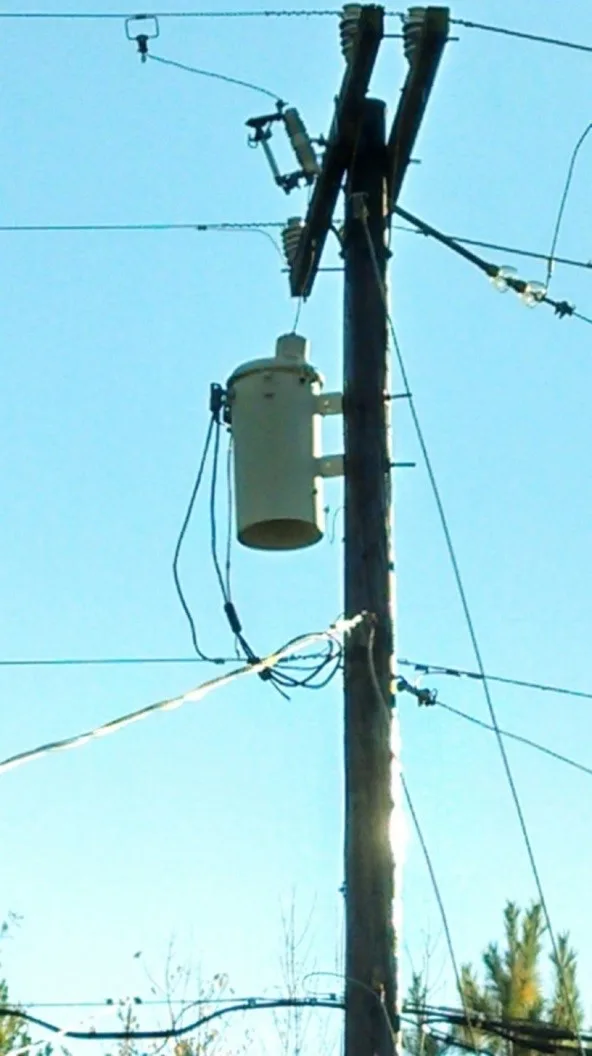
Figure 3. Single-phase AC electrical power distribution systems
As illustrated in Figure 4, the single-phase transformers are normally rated 3-wire at 120/240 volts. The connected loads can be supplied as a 2-wire branch circuit at either 120 volts (ungrounded supply and a common grounded return ― the neutral conductor) or 240 volts (ungrounded supply and return), or as a 3-wire branch circuit with both voltages.
The electric clothes dryer or stove (cooking range) in the average home is supplied with a single-phase AC, 3-wire, 120/240-volt branch circuit (multi-wire ― both of the ungrounded supply conductors and the common grounded neutral return).

Figure 4. Voltage relationships of the three secondary supply lines
In terms of power calculations of a single-phase AC circuit, the apparent power available from a feeder or branch circuit is simply the product of line voltage times line current. By formula:
Volt-Amps (VA) = VLINE × A LINE
Or, kilo-Volt-Amps (kVA) = (VLINE × A LINE) ÷ 1000 (/k)
The apparent power available from a single-phase AC, 3-wire, 120/240-volt branch circuit is calculated at the higher line-to-line voltage of 240 volts.
Single-Phase AC Power Key Takeaways
Understanding the principles of single-phase AC power generation, waveform behavior, voltage configurations, and power calculations is essential for designing and maintaining reliable electrical systems. These concepts play a critical role in residential, commercial, and industrial applications, where efficient power distribution, accurate measurements, and proper load handling are vital for safe and effective energy use.