This article provides an overview of water turbine, discussing their classifications into impulse and reaction types and their specific applications based on water flow and head conditions. It highlights various turbine designs, including Fourneyron, Francis, Kaplan, Pelton, Turgo, and crossflow turbines, emphasizing their unique operational principles and efficiency factors in hydroelectric power generation.
Almost all electrical power is produced with some type of turbine. Water turbines are different than the steam turbines used in most conventional power plants. This section includes a general discussion of water turbines and specific types used for converting hydropower to the mechanical rotating motion.
The specific conditions of the head and flow largely determine the type of turbine that produces the most efficient operation in a given situation.
Ideally, a water turbine should transfer all of the kinetic energy in moving water into turning the shaft. While it is not possible for any mechanical device to be 100% efficient, well-designed water turbines can have very high efficiencies.
The key to high efficiency is to minimize losses such as those resulting from turbulence, vibration, or heat.
To minimize turbulence, the turbine blades must be smooth and the turbine must be well balanced with low-friction bearings.
An equation by the famous mathematician Leon Euler in 1754 is still used today by engineers to calculate the power from water turbines.
The equation basically indicates that the power from a turbine is equal to the product of torque on the shaft and the rotational speed.
Torque is the product of a force, F, and the perpendicular distance, x, from a fixed point that tends to produce rotation about the point; it is measured in newton-meters in the SI system and pound-feet in the English system. Torque is illustrated in Figure 1.
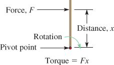
Figure 1 Definition of Torque. A force, F, acts on a body at a perpendicular distance, x, from a pivot point that tends to produce rotation.
Impulse and Reaction Turbines
Water turbines are defined by the form of energy they convert to mechanical motion. Turbines are classified as either IMPULSE TURBINE or REACTION TURBINE; most turbines are a mixture of the two classifications.
Impulse Turbine
An impulse turbine is a rotary engine that changes the direction of a high-velocity fluid, thus converting kinetic energy into mechanical rotating energy.
In an impulse turbine, water is passed at high velocity (thus high kinetic energy) through a nozzle and focused on the turbine blades, causing them to rotate.
Impulse turbines are like a pinwheel. As water hits the blade of the turbine, called a runner, the blade is pushed.
Impulse turbines are used most often in applications with high-pressure heads and relatively low flow. The head is typically in excess of 300 m. Figure 2 shows a basic impulse turbine.
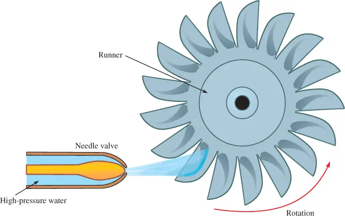
Figure 2 Impulse Turbine Diagram
Reaction Turbine
A reaction turbine is a rotary engine that develops torque by reacting to the pressure of a fluid moving through the turbine, thus primarily converting potential energy into mechanical rotating energy.
In a reaction turbine, the rotating blades are completely encased in a pressure encasement and the fluid flows through a fixed guide mechanism onto rotating blades.
Unlike an impulse turbine, the reaction turbine does not have nozzles. Water has both potential energy due to its pressure and kinetic energy due to its motion, but the primary mover is the pressure drop, which creates the reaction force.
Due to the importance of water pressure in this process, the reaction turbine must remain submerged at all times. This stipulation often requires that the turbine is encased in water if the water levels at the site are not consistent.
Most reaction water turbines are used with low or medium heads but with a larger volume of water.
Turbines can also be subclassified as radial design or axial design.
In a radial-flow turbine, the flow enters in the direction the turbine moves and exits along the axis of rotation. In an axial-flow turbine, the flow enters the turbine in the direction of the axis of the shaft and leaves the turbine in the same direction.
Types of Water Turbines
Impulse and reaction turbines are further divided into specific types of turbines. The type of turbine selected for a given application depends primarily on the flow and head. The following subsections discuss each type.
Fourneyron Turbine
A French engineer named Benoit Fourneyron developed the first reaction turbine in 1826, which is the predecessor to most turbines used in hydroelectric power plants.
Fourneyron’s turbine is a horizontal outward radial-flow waterwheel. His turbine was an advancement of a design created originally by his teacher Claude Burdin, which produced approximately 40 horsepower (hp).
In 1837, Fourneyron improved the design and patented a 60 hp turbine that was approximately 30 cm in diameter.
The turbine he designed was a reaction turbine that rotated at 2,300 revolutions per minute (rpm), and it could handle a wide range of heads: less than 1 m to 3 m and as high as 30 m at efficiencies up to 85%, which was much higher than the open waterwheel designs of his day.
The Fourneyron turbine is shown in Figure 3. It used fixed guide vanes to direct water onto the moving runner blade with buckets that rotated and produced energy.
The Fourneyron turbine operates completely submerged, which ensures that it has a smooth flow of water, thus creating a highly efficient design.
The water flows from the inside through the fixed guide vanes and splashes against the moving outside wheel, which spins, thus producing the power.
Today, the more efficient Francis and Kaplan turbines have largely replaced their predecessor as the reaction turbines of choice.
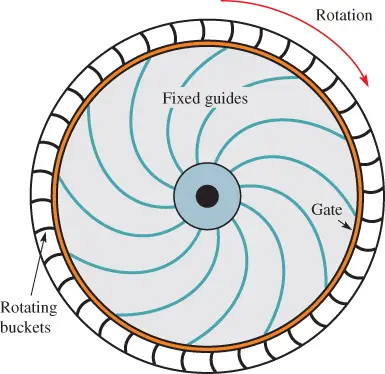
Figure 3 Top View of a Fourneyron Radial-Flow Water Turbine.
Francis Turbine
In 1849, James B. Francis improved a design on a radial inward-flow reaction turbine so that it produced power at over 90% efficiency.
The Francis turbine is the most widely used water turbine in the world today.
Unlike its predecessor, the Fourneyron turbine, water is directed from the outer circumference toward the center of the runner, which is the rotating center part of the turbine.
Water from behind a dam flows through the guide vanes on the sides of the turbine, spins the runner, and exits through the bottom tailrace tube. Figure 4 shows the runner.
The vanes are in a scroll case, which is a curved tube that diminishes in size, in a shape similar to a snail shell.
The Francis turbine is used for medium head (30 m to 300 m) applications. Today, the Francis turbine is installed with a range of power outputs, from 1 kW to 820 MW.
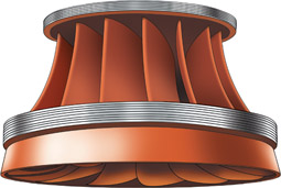
Figure 4 Runner for a Francis Turbine
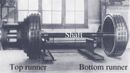
Figure 5 A Fourneyron turbine diagram from the Adams Power Station at Niagara Falls, New York. The turbine was installed with the shaft oriented vertically.
Although small hydroelectric power plants existed earlier, the first successful, commercial hydroelectric plant in the United States was on the US side of Niagara Falls in New York State.
Three Fourneyron turbines of 5,000 hp and 250 rpm were installed in 1893, making it one of the first power plants to use renewable energy.
Today, Niagara Falls still generates power—currently, it uses thirteen generators and develops over 2,500 MW of power.
Kaplan Turbine
The Kaplan turbine, an evolution of the Francis turbine, is shown in Figure 6. It is a reaction water turbine that uses propellers with adjustable blades. The turbine is usually placed in a spiral-shape casing called a volute.
It was developed by Austrian engineer Viktor Kaplan in 1913 and is generally considered for low-head, high-flow applications.
By changing the pitch angle of the blades in tandem with the angle of the turbine, the Kaplan turbine can maintain a high efficiency even at very low flows.
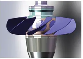
Figure 6 Kaplan Turbine Diagram
As in all reaction turbines, a drop-in pressure occurs as water passes through the Kaplan turbine. There is pressure on the upstream side of the turbine runner and suction on the downstream side.
On the downstream, or outlet, side of the turbine is the draft tube, which connects the turbine to the tailrace.
The tailrace is the channel leading away from the turbine. The draft tube has a unique curved hornlike shape that slows the water as it exits the turbine.
The Kaplan turbine has an efficiency curve that changes little with flow rate, so it is particularly suited to rivers where the amount of water flow varies greatly.
The Kaplan turbine is often used for run-of-the-river power stations. Propeller turbines can reach very high rotation speeds that work well in very low head applications.
Figure 7 shows a basic installation of a Kaplan turbine in a power station.

Figure 7 Generator Driven by a Kaplan Turbine
Pelton Turbine
The Pelton turbine in the photo is from the hard rock, gold mining days in California when power was needed for the underground mines.
The Pelton turbine shown here was removed from the NorthStar Mine powerhouse. Figure 8 shows a historic Pelton turbine.
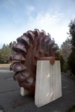
Figure 8 Historic Pelton Turbine
The Pelton turbine (also called a Pelton wheel) is an impulse turbine whose runner has a number of cup-shaped containers connected around its circumference.
The runner is connected to a central hub that rotates and transmits energy to a shaft, as shown in Figure 9.
Nozzles are positioned around the runner so that water flow is directed into the cups. When the water strikes the cups, it changes the potential energy of the water into kinetic energy by pushing the turbine wheel around.
Pelton turbines have been modified over the years with different types of the cup-and-wheel apparatus. Each modification has made the Pelton turbine more efficient.
The turbine is known today as the Pelton turbine was first designed by Samuel Knight in 1866, who worked as a millwright in California. He patterned his design after a high-pressure jet system used in mining gold, and his turbine was called the Knight wheel.
The turbine uses a high head, over 30 m, where water drops into the cup-shaped containers. The force of the water provides kinetic energy that moves the runner.
As the runner rotates, the container carries the water until it reaches the other side of the runner, where the container is inverted and the water is released out of it at a much lower velocity.

Figure 9 Pelton Turbines at Walchensee Power Plant in Germany
In 1879, the turbine that was originally designed by Samuel Knight was improved by Lester Pelton at Grass Valley, California.
As Pelton watched the Knight wheel spin, he noticed that it had slipped out of its normal position and was offset, yet it seemed to spin faster.
When it slipped, the cups became out of position so that water hit the cups near their edge instead of in the middle of the cup, which made the wheel more efficient.
Pelton designed an improved waterwheel that had the cups aligned so that water would hit near their edges, and he included a double set of buckets that were side by side. This split the water jet in two.
The water does a U-turn in Pelton’s design, thereby extracting nearly all of its kinetic energy.
In 1895, William Doble (who worked for Pelton) made a further refinement to Pelton’s design by replacing the half-cylindrical buckets with buckets that were elliptical in shape. His buckets included a cut to force water more efficiently into each bucket.
Doble’s variation of the Pelton turbine can achieve up to 92% efficiency. Doble later took over the Pelton Company and did not change the name of the turbine because of the Pelton brand recognition.
Pelton turbines are still preferred where there are a high head and a low-flow rate. Figure 9 shows Pelton turbines at Walchensee Power Plant in Germany. You can see the double cups in the new turbines.
Turgo Turbine
The Turgo turbine is a compact impulse turbine that was developed and installed in Scotland in 1919 by Gilbert Gilkes as an update to the Pelton turbine.
The Turgo turbine uses half cups around the runner instead of full cups, like the Pelton turbine (see Figure 10 for a close-up of the cups).
The half cup on the Turgo turbine allows water to enter and exit each cup faster and in larger amounts than with Pelton turbines, so it is better suited for higher flow rates.
Water for the Turgo turbine flows through one or more nozzles directly onto the cups. Increasing the number of jets increases the speed of the runner by the square root of the number of jets.
For example, if four jets are used, they will yield twice the specific speed as one jet on the same turbine.
The Turgo turbine is usually used in applications where there is low to medium flow and with heads that are medium to high. It can be mounted horizontally or vertically.
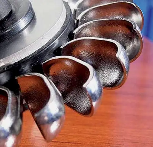
Figure 10 Closeup of the Cups on a Turgo Turbine
Crossflow Water Turbines
The crossflow water turbine is a drum-shape impulse turbine. It is designed with long trough-shape blades (or horizontal slats) in a radial arrangement around a cylindrical runner, as shown in Figure 11.
The turbine uses two spray nozzles to direct water flow at a 45° angle across the blades or one large wide rectangular water jet.
Water striking the blades converts its kinetic energy into rotational energy. The flow of water is controlled to maintain the desired speed of the runner.
In operation, water is sprayed onto the blades, and most of it then enters the turbine and passes through the blades again as it exits.
Crossflow turbines are used in smaller hydroelectric applications where the maximum power output typically does not exceed 2,000 kW and costs are critical. The head is usually between 10 m and 150 m, but the flow is relatively high.
The average efficiency is about 80% for smaller units and 86% for larger ones.
Because the water passes through the turbine across its blades, the water provides power once when it enters the blades and again as it leaves the blades on the opposite side, which improves its efficiency.
When compared to the Pelton, a crossflow turbine of similar size can handle a greater amount of water flow.
The crossflow turbine is known by two other names: the Michell-Banki turbine and the Ossberger turbine. It was originally designed in 1903 by Anthony Michell.
Donat Banki, a Hungarian professor, later improved the design and received a patent around 1925.
In 1933, Fritz Ossberger, a German engineer, improved the patent, and the turbine remains much the same today.

Figure 11 Crossflow Turbine Components Diagram
Table 1 summarizes the types of water turbines discussed in this section.
| Reaction Turbines | Impulse Turbines |
| Fourneyron | Pelton |
| Francis | Turgo |
| Kaplan (propeller) | Crossflow (also called Michell-Banki or Ossberger turbine) |
Water Turbine Review Questions
- Explain how an impulse turbine operates.
- Explain how a reaction turbine operates.
- List three types of reaction turbines.
- List three types of impulse turbines.
Answers
- An impulse turbine has water moving with high kinetic energy through a nozzle aimed at turbine blades to cause them to rotate.
- A reaction turbine creates torque by reacting to the pressure of a fluid moving through the turbine, thus converting potential energy to kinetic energy.
- Three reaction turbines are (1) Fourneyron, (2) Francis, and (3) Kaplan.
- Three impulse turbines are (1) Pelton, (2) Turgo, and (3) crossflow.
Water Turbine Key Takeaways
Understanding the types and principles of water turbines—impulse and reaction—is essential for designing efficient hydroelectric systems tailored to specific environmental conditions like head and water flow. The classification and operational nuances of turbines such as Pelton, Francis, Kaplan, Fourneyron, and Turgo are not just academic; they play a vital role in optimizing energy production. High-efficiency water turbines are crucial in converting the natural force of moving water into usable mechanical and electrical power, especially in renewable energy projects. These technologies contribute significantly to sustainable development, energy independence, and environmental conservation by reducing reliance on fossil fuels.